You are correct. I didn't notice they where different than the other op-amps. The voltage reading on power supply pins of both the Ne5534s is +12.83v and -13.07v
Does the signal remain clean on pin 3 of the NE5534 after it starts to clip at the speaker output?
It is difficult to be certain as the amp output has dropped so low as to not produce a signal/wave form. I only get a second of a waveform when I turn the amp on. In that time it appears the signal on pin 3 is remaining clean.
I hooked it to a speaker to the amp and it is putting very little sound.
Not sure if you seen back on post #7 where I mentioned the two voltage regulators I circled in the photo are getting hot.
I hooked it to a speaker to the amp and it is putting very little sound.
Not sure if you seen back on post #7 where I mentioned the two voltage regulators I circled in the photo are getting hot.
Is the amp shutting down?
Regulators can get hot at idle. Some get so hot that they fail within seconds. If they are producing output and are no shutting down, I wouldn't be concerned. That said, if you're concerned, clamp them to the main heatsink or to a piece of aluminum stock (with insulators) to keep them cool.
Regulators can get hot at idle. Some get so hot that they fail within seconds. If they are producing output and are no shutting down, I wouldn't be concerned. That said, if you're concerned, clamp them to the main heatsink or to a piece of aluminum stock (with insulators) to keep them cool.
No the amp is not shutting down. I have never seen the voltage regulators get hot on a properly functioning amp when running it on my power supply. The other side voltage regulators are not even getting warm. My thoughts were that there is something wrong in that circuit and why I mentioned it. I do have the amp clamped.
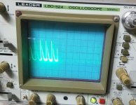
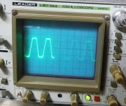
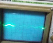
What are your thoughts on what my scope is doing? When I first power it on, the screen looks like the first photo. After it starts warming up the the waveform slow starts getting smaller until eventually it is a flat line. After that it seems to function basically as it should.
As to your question in post #22: As I mentioned, now when I power the amp up it only produces a waveform form for about 30 seconds. After that, if I shut it down and turn it back on it only produces a waveform for about one second. If I let it sit for 10 minutes it is back to square one again. Catching from the start the signal on pin 3 of the NE5534 looks to be staying clean.
As to your question in post #22: As I mentioned, now when I power the amp up it only produces a waveform form for about 30 seconds. After that, if I shut it down and turn it back on it only produces a waveform for about one second. If I let it sit for 10 minutes it is back to square one again. Catching from the start the signal on pin 3 of the NE5534 looks to be staying clean.
Attachments

I don't know what's wrong with the scope. I only know what I have to know to keep mine running.
Are any of the rail or regulated supply voltages changing significantly as the amp goes from producing output to producing virtually none?
Are any of the rail or regulated supply voltages changing significantly as the amp goes from producing output to producing virtually none?
The rail or regulated supply voltages are not changing at all when as the amp goes from producing output to virtually none.
When the amp starts to clip, the output of the 5534 should go from a slightly distorted sinew wave to a highly distorted waveform that swings to the supply rails of the 5534. Is that what you're seeing on the output terminal of the 5534?
I'm not sure that I completely understand that. If you could explain a little more would help.
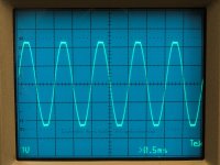
I attached photo's of the wave form on the output of the 5534. Starting with it not clipping to clipping. I noted during this that when the amps drops down to virtually no out put I also loose signal on the output pin of the 5534.
I attached photo's of the wave form on the output of the 5534. Starting with it not clipping to clipping. I noted during this that when the amps drops down to virtually no out put I also loose signal on the output pin of the 5534.
Attachments
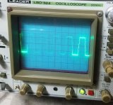
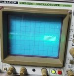
The image on the right shows the drive from pin 7. It's a rough sine wave up to the point when the amp starts clipping.
The left image is feedback from the output of the amplifier that's driving pin 6 of the 5534.
When the amplifier starts to clip, the drive signal goes from a sine wave-ish signal at a relatively low level (about ±5v) to a large spike (as far as the op-amp can drive) as it tries to compensate for the distortion caused by the output reaching the rail voltage.
Attachments
Thank you for explaining that. To be clear on which pin I should be testing is pin 6 of the 5534, right?
Let me try that again. The pin numbering was from a different amp, not using a 5534.
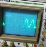
The left image is the feedback, showing distortion from clipping. This is driven back into the inverting input of the op-amp (pin 2 of the 5534). The right image shows the output of the op-amp (pin 6 of the 5534).
What you should be looking for it input to the op-amp that remains clean (pin 3 of the 5534) and an output on pin 6 that drives as far as possible at the onset of clipping (visible on pin 2 of the 5534).
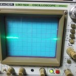
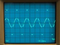
The photos in post #30 are of pin 6 of the 5534. The attached photo is of pin 2 of the 5534 at the onset of clipping.
Sorry about the blurriness of the photo. It is difficult to get a photo with only having a few seconds in which to take it before the amp drops output.
Sorry about the blurriness of the photo. It is difficult to get a photo with only having a few seconds in which to take it before the amp drops output.
Attachments
When photos of waveform are posted, the scope settings need to be included.
Unless you're 100% sure that the scope is relatively close to being calibrated, touch the B+ terminal to confirm that the deflection agrees with the settings.
What was the vertical amplifier setting in post #30?
Unless you're 100% sure that the scope is relatively close to being calibrated, touch the B+ terminal to confirm that the deflection agrees with the settings.
What was the vertical amplifier setting in post #30?
My next suggestion would be to lift the 2.7 resistor on the output of the 5534 (if this is like most older Orion amps) and inject a signal into that resistor from the output pin from another op-amp on the board. Pick any op-amp that you can drive to produce at least a couple of volts.
I've never tried this but it shouldn't cause any problems. Run a jumper wire from the good op-amp to the 2.7 ohm resistor. Be prepared to quickly disconnect power if it draws excessive current. Start with the volume at 0 and slowly increase it. The output will be somewhat distorted. What I want to know is whether the output remains steady or if it drops off as when driven by the 5534.
I've never tried this but it shouldn't cause any problems. Run a jumper wire from the good op-amp to the 2.7 ohm resistor. Be prepared to quickly disconnect power if it draws excessive current. Start with the volume at 0 and slowly increase it. The output will be somewhat distorted. What I want to know is whether the output remains steady or if it drops off as when driven by the 5534.
I had started thinking the output falling off seemed very reminiscent of the muting system problem you had helped me with on the Orion HCCA 225 quite sometime back. So I pulled the two muting transistors back out of the board and the output is no longer falling off. The distortion is still there.
Also found the the distortion is a little worse on the left channel than the right channel.
Also found the the distortion is a little worse on the left channel than the right channel.
Last edited:
- Status
- Not open for further replies.
- Home
- General Interest
- Car Audio
- Needing help repairing an Orion HCCA 250 Digital Reference