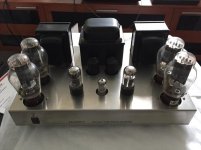
I just got this one yesterday for $200 but couldn't find schematic anywhere. Not sure if it's PP or SE
1. Not sure how to bias and where to check the voltage
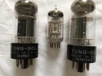
2. Is it 6SN7 since I don't see the label
3. Low level consistent humming
4. Loud humming when DAC connect, no problem with SS amp
So far everything is working great with other audio except DAC gives a loud humming when connect
Do you think upgrade the coupling caps would make it better? I have PIO caps around, I think I may try since it's a PCB.
1. Not sure how to bias and where to check the voltage
2. Is it 6SN7 since I don't see the label
3. Low level consistent humming
4. Loud humming when DAC connect, no problem with SS amp
So far everything is working great with other audio except DAC gives a loud humming when connect
Do you think upgrade the coupling caps would make it better? I have PIO caps around, I think I may try since it's a PCB.
Attachments


Do you have a multimeter that gives resistance readings? That will help figure out PP or SE question and where to check bias.
PIO: question of taste. Technically the worst film capacitors you can get.
PIO: question of taste. Technically the worst film capacitors you can get.
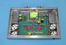
It's push-pull. Looks to have had some modifications already.
The hum that appears with your DAC connected is likely a ground loop. You may be able to minimise it by powering both from the same AC outlet.
The hum that appears with your DAC connected is likely a ground loop. You may be able to minimise it by powering both from the same AC outlet.
I do have have resistor multimeter
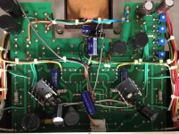
If it's PP, should it have 2 coupling caps? I saw only 1 each channel
All the setup are the same with the DAC when tested with SS and Tube amps. No problem with cd, phono, dvd, etc.
If it's PP, should it have 2 coupling caps? I saw only 1 each channel
All the setup are the same with the DAC when tested with SS and Tube amps. No problem with cd, phono, dvd, etc.
I was looking at a few 300B PP schematics and all of them have 2 coupling caps since this one has only 1. Not sure why that web said Golex PP 300b
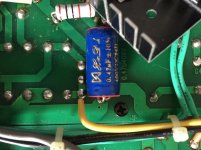
1. I think the cap (with the red ends) you can see is the decoupling cap of a cathode coupled phase splitter.
2. There seem to be more stages than necessary for an SE design.
2. There seem to be more stages than necessary for an SE design.
The coupling caps could be on the other side of the board. But you can have 1 coupling cap for a pushpull amp:I was looking at a few 300B PP schematics and all of them have 2 coupling caps since this one has only 1
Attachments
I haven't removed the PCB yet so don't know what it's on other side but I don't think any caps since it's very close to the chassis. Maybe a few of resistors or something.
Yeah that the 2 coupling caps, 1 for each channel. I thought it's support to be 2/channel for PP
A lot of designs I was looking at have 2, barely see any PP has 1. What is the advantage/disadvantage as an optional?
Yeah that the 2 coupling caps, 1 for each channel. I thought it's support to be 2/channel for PP
A lot of designs I was looking at have 2, barely see any PP has 1. What is the advantage/disadvantage as an optional?
Attachments
Yes, yours have been heavily modded, but at least you know now it’s a PP design. What’s the part number of the transistor or IC in your amp?

UA7906C by TI is a -6volt 1.5amp fixed regulator.
Might be for the filaments on the small signal tubes. You need to trace the circuit to find out.
Looking at your images more closely they appear to be connected to the filament pins of the 6SN7s.
Steve
Might be for the filaments on the small signal tubes. You need to trace the circuit to find out.
Looking at your images more closely they appear to be connected to the filament pins of the 6SN7s.
Steve
Alashikata,
Bas Horseman posted a schematic in post #9. It is a Push Pull amp featuring the Self Inverting Output Stage. Advantage: simplicity. You will find some of these style amps on the web. OddWatt (spelling?) Kits are examples.
These self inverting output stages are Class A outputs; they can not operate in Class AB, nor 'as Class AB'.
I have built a few push pull amplifiers of my own design with self inverting output stages. I have used Bipolar Transistor current sinks in the output stage cathode circuit. And I have used Chokes as current sinks in the output stage cathode circuit.
Put a constant current device in the plate circuit, and call it a constant current Source. Put a constant current device in the cathode circuit, and call it a current Sink. Or, do like most do, call both of them a constant current source (CCS).
Last edited:
Thank you ArcticBrew, it connected to the filaments for the 6SN7
I looked at the OddWatt amp, his design still has 2 coupling caps. I have searched and found some chinese website(google translation helps lol) has the info and some pictures have 2 coupling caps too. Mine seems like it has been modded with the filaments and coupling caps.
Here is the info from the chinese webiste " GOLDOX Taurus brand stainless steel tube amp GOX-300B : database storage product not used, 12AX7 × 1 + 6N8P × 2 + 300B dawn tubes × 4, broadband sound card Taurus push-pull output transformer, power of 2 × 25W, frequency response 10Hz ~ 50KHz ±1.5db, signal-to-noise ratio 95db, 4 ohm/8 ohm gold-plated speaker posts, gold-plated RCA socket. The filaments are all AC power supply, the noise is small........"
So as they mentioned on the chinese website, there is a small hum which I probably won't able to fix it. I will take out the PCB next Monday to see what it's on the other side which I think a few resistors and diodes. Then swap out the PIO caps only since everything is working fine. Will take a look at the coupling caps later if I have time to trace down all the traces.
Here’s the schematic:

I would remove all the existing mods and restore the amp to its original condition before thinking about “improving” it.
I would remove all the existing mods and restore the amp to its original condition before thinking about “improving” it.
Thank you so much jazbo8  Where did you get the schematic? I have tried a lot of chinese website with google translate but couldn't find anything much except description. I will check out the coupling caps first.
Where did you get the schematic? I have tried a lot of chinese website with google translate but couldn't find anything much except description. I will check out the coupling caps first.Alashikata,
This is what I was talking about: OddWatt S2 model, schematic with Only 1 coupling cap; not Poddwatt schematic on the same link. It also uses one negative feedback cap; and one input stage bypass cap. (all 3 caps are different capacitance values, and all different voltage ratings). Link: Poddwatt: Class-A Stereo Push-Pull EL84 (6BQ5) Vacuum Tube Amplifier
Sometimes one control grid of a push pull or balanced amplifier is returned to ground by a resistor of equal value as the other control grid, to maintain DC balance. But if one grid is not driven by an inverted signal, that grid resistor to ground is bypassed, In order to correct for the miller capacitance effect. That is the case of this amp: (The amp schematic may have been updated over time. Now the second 0.22uF “coupling cap” is actually a “bypass cap” for the second 220k grid resistor. It is not a signal “coupling cap” **). Link: OddWatt Audio 5751 SRPP / KT88 Push-Pull Monoblock Tube Amplifier Kits
And jazbo8's schematic shows there are 2 (two) coupling caps in the original 300B push pull amp. By the way, C3 in that schematic is another example of what I was talking about at ** above.
It appears you either have second coupling caps hidden somewhere, or someone modified your amp to use a self inverting output stage, like 'some' of the OddWatt amps.
Have fun getting the amp running smoothly, and sounding good.
Last edited:
- Home
- Amplifiers
- Tubes / Valves
- Need schematic for this 300B to improve