A ha, thank you, I was looking at a wrong one "Odd Block KT88 Series 1 Tube Amp Kits". Got it.
Since jazbo8 got the schematic, i will look into it later to see where someone did the mod on this amp. While it's working fine, I would swap the PIO caps first to see what happen. If everything is going well, then I may keep as it. However, i will take the PCB out to take picture on the other side to see any mod on it.
Does any know how to check the bias on this amp? Is it the pin 3?
In fixed bias, the bias on a 300B is from pin 3 grid, to the filament (the center tap of the resistors in the filament circuit). The filament circuit will be near to 0V to ground
In self bias, pin 3 of the 300B is at zero volts. Bias is the voltage from the center tap of the filament circuit versus ground.
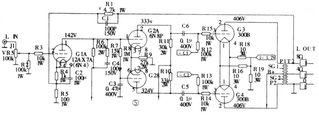
I am not sure what kind of bias your amp uses. jazbo8's schematic is fixed bias. R19, the 10 Ohm resistor is the current sense resistor. It has 1V/100mA. Two 300B's with 50mA each would have 100mA total, and 1V across R19.
If the grid, pin 3, is quite negative, several 10's of volts, it is probably fixed biased.
If the grid, pin 3, is at 0 Volts, then the filament circuit is probably several 10's of volts positive, then it is probably self biased.
There are a few 300B's that are both fixed and self biased (some of both methods).
In self bias, pin 3 of the 300B is at zero volts. Bias is the voltage from the center tap of the filament circuit versus ground.
I am not sure what kind of bias your amp uses. jazbo8's schematic is fixed bias. R19, the 10 Ohm resistor is the current sense resistor. It has 1V/100mA. Two 300B's with 50mA each would have 100mA total, and 1V across R19.
If the grid, pin 3, is quite negative, several 10's of volts, it is probably fixed biased.
If the grid, pin 3, is at 0 Volts, then the filament circuit is probably several 10's of volts positive, then it is probably self biased.
There are a few 300B's that are both fixed and self biased (some of both methods).
Last edited:
I was watching couple youtube video of 300b bias but wasn't clear much which point to check. So even a fixed bias, I can check the pin 3 and the center tap of the resistors in the filament circuit?
There are 4 trim pots on the PCB so I thought it's for bias. Now I see that jazbo8's schematic doesn't have the trim pots resistors while all the pics on chinese websites show the trim pots. I may have to trace down all the points. If it's fix bias, I don't have to worry anything. 🙂
There are 4 trim pots on the PCB so I thought it's for bias. Now I see that jazbo8's schematic doesn't have the trim pots resistors while all the pics on chinese websites show the trim pots. I may have to trace down all the points. If it's fix bias, I don't have to worry anything. 🙂
All turned off, and Unplugged, and allowed time for the voltages to go to zero (check with your DC voltmeter from various points to ground; i.e. from 300B pin 2 plate to ground, etc.).
1. After the amp has been turned off for several minutes, and the voltages are 0, you can use your Ohmmeter to check from the filament pin 1 to ground, and from the filament pin 4 to ground. If the Ohmmeter readings are just from about 1 to 100 Ohms, it seems to be fixed bias. If the Ohmmeter reading is from about 300 to 1k Ohms, it seems to be self bias. If it is self bias, then you can test from pin 1 of one 300B to pin 1 of the other 300B in the push pull pair, and see if they are connected (low Ohms, 0 to perhaps 50 Ohms). This would be Common self bias.
If it is self bias, then you can test from pin 1 of one 300B to pin 1 of the other 300B in the push pull pair, and see if they are Individual self bias (about 500 Ohms to 2k Ohms). If the pots are for fixed (adjustable fixed) bias, then each 300B bias has to be set individually. Your major number one problem with the amplifier wired as it is, is that until you make a complete and accurate schematic of how it is now, it is only a guess as to answering questions about the state and condition that it is in, and what you might retain or change.
Last edited:
Very helpful. I will do that next Monday and swap out the PIO caps to see how good it's. 🙂
Thank you 6A3sUMMER,
Thank you 6A3sUMMER,
Jazbo8's schematic does not include the bias pots, because the power supply (including the bias supply) is not included in the schematic.The schematic is for a fixed bias (and likely adjustable fixed bias) output stage.
Look at -C1 and -C2 on the schematic, that is where I expect the pot wipers would connect.
Look at -C1 and -C2 on the schematic, that is where I expect the pot wipers would connect.
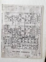
You are welcome, no idea where I got it from, found it on my hard drive... As for the bias network, here is the typical scheme used by Goldox, Sparks, Audio Space, etc.:Thank you so much jazbo8Where did you get the schematic?

The parts values can be seen/measured in your amp.
There are a few 300B's that are both fixed and self biased (some of both methods).
IMO, there is much to be said for combination biased DHTs. Power triodes, like the 300B, are especially vulnerable to run away from unwanted grid leak biasing effects, when "fixed" bias is employed. So, the total grid to ground resistance must be kept comparatively small. In turn, that low impedance creates problems for the driving small signal circuitry. Employing a cathode resistor to generate part of the total bias voltage stabilizes the operating point and safely allows a modest increase in the total grid to ground resistance. A 100 Ω resistor bypassed by a 470 μF. cap. makes a convenient "idle" current setting test point.
Not bypassing the cathode resistor will linearize the DHT (IMO a good thing), but the increase in O/P impedance has to be accounted for in the primary of the O/P "iron" and the B+ rail voltage.
IMO, there is much to be said for combination biased DHTs. Power triodes, like the 300B, are especially vulnerable to run away from unwanted grid leak biasing effects, when "fixed" bias is employed.
2 ducks by a single shot: efficient use of the tube in A2, and no run away with fixed bias.
Edit: 3, actually: eliminating influence of Miller capacitance.
Attachments
Last edited:
Finally, I got it fixed. I didn't have time when I started this thread while working on remodel the house so I left it on the side to complete the house first. I went on YouTube and search around and found Mr. Young Ahn from Fluxion company that helps me to fix the hum problem. It was the wrong bias and too high too. No longer has hum on the speakers and the hum on PT is barely hear unless stand close to the amp.
Sound is sweet now. I replaced 300B chinese made with EH GOLD Platinum 300B and Tung-Sol 6SN7GTB where most people like. It sounds better than the chinese made. I keep MAZDA CHROME PLATE 12AX7 as it, not sure if I want to get different brand. I hear 12AU7 is good too so I may buy to try it out. Also replaced 6 Russian PIO caps while working on the amp.
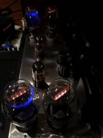
By the way, the new 4 EH GOLD Platinum 300B I bought, 2 of them have Blue Glow. Is it gonna effect the life of them? I was asking the seller but he said it's normal.
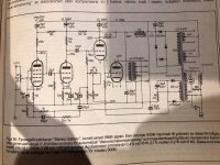
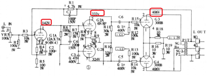
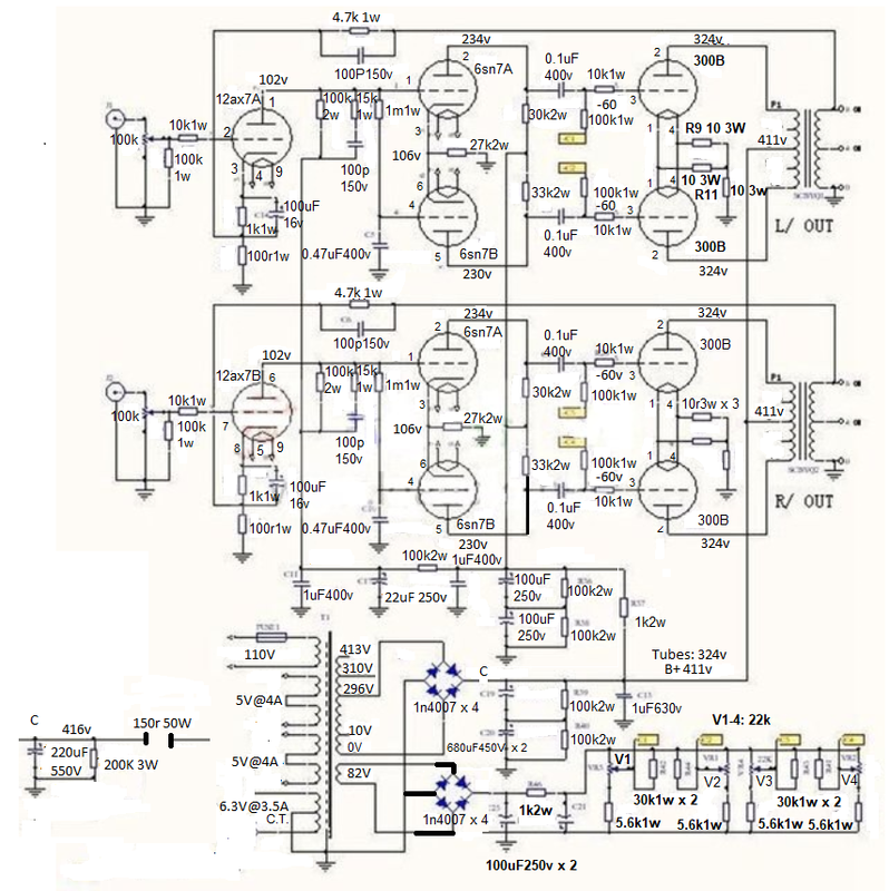
I think I am going to build another one for Bi-Amp with this schematic but I need to find out what the OPT and PT are. Does anyone see the value of PT on the schematic below. That's the only image I found below.
Sound is sweet now. I replaced 300B chinese made with EH GOLD Platinum 300B and Tung-Sol 6SN7GTB where most people like. It sounds better than the chinese made. I keep MAZDA CHROME PLATE 12AX7 as it, not sure if I want to get different brand. I hear 12AU7 is good too so I may buy to try it out. Also replaced 6 Russian PIO caps while working on the amp.
By the way, the new 4 EH GOLD Platinum 300B I bought, 2 of them have Blue Glow. Is it gonna effect the life of them? I was asking the seller but he said it's normal.
I think I am going to build another one for Bi-Amp with this schematic but I need to find out what the OPT and PT are. Does anyone see the value of PT on the schematic below. That's the only image I found below.
Attachments

Do I need to readjust the voltage for the driver? After spending time tracking all the parts, it was exactly as the schematic below. However, I am not wise sure about the driver voltage.
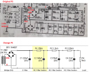
I have reworked the PS and no room for choke so I use C, RC. B+= 417v and bias = 92v. All heaters are AC but no hum. Actually, the hum was fixed with 22 ohm 3w resistor from main ground to chassis. House ground to chassis. If connect house ground to main ground, it will create a hum. It was great except small buzz on PT, not sure how to fix it.
Without tubes, B+ is 417v and 410v at plate, 323v, and 154v. Seem like perfect. However, when inserts in the tubes, the plate is 325v with bias -60v where all the voltage at PS drops. The driver voltage 333v becomes 235v and 141v equals 88v. I wonder if I need to push the voltage after B+ up for driver as in the pictures?
Cannot really read your schematics. It's too small and if I try to magnify it it's all smeared. The link to the image above doesn't work for me.
What is the plate voltage and anode current for the drivers with all tubes in? What the bias and anode current for the input tube with all tubes in?
Is this class A or class AB?
What is the plate voltage and anode current for the drivers with all tubes in? What the bias and anode current for the input tube with all tubes in?
Is this class A or class AB?
Sorry, here is the schematic.
Plate voltage without tubes: 417v
With tubes, all voltages drops: plate "323v"
I am not sure class A or AB since I don't have document. Plate voltage drops because of bias so I think it's fine but the driver voltage drops as well so i am not sure if I need to increase the driver voltage to 333v and 142v
Attachments
Here is my rewire the power supply since it's 110v, so I have to use variac to adjust from 120v outlet.
I did test for an hour without any problem. Look like the bass sounds pretty good than the midrange so I don't know because of the driver voltage is not correct or what.
I did test for an hour without any problem. Look like the bass sounds pretty good than the midrange so I don't know because of the driver voltage is not correct or what.
Attachments
First, you are using fixed bias. I cannot see any significant cathode bias in your circuit except those 10R small resistors. This means you are running the tubes at 325V with 60 negative bias which is a bit hot for a true 300B!
The input stage looks ok at 142V anode voltage + self-bias. The driver stage, the anode voltage should be around 190V (if supply is 333V) which should ok as well but the current is a bit on the low side at about 7 mA total (3.5 mA per tube if they are identical). The anode load for the driver stage is 23K. Then I am not sure how balanced is the LTP with 6N8P without a CCS in the tail. So if the bias of the 300B's is 60V and the amp works in class A, which should the case if they are running quite hot, it's just enough but distortion might go up quickly approaching max output because of the driver stage close to running out of current. If this voltages drop when you have tubes it's no good.
For Class AB operation I doubt you get all the possible output power without significant distortion.
The fact that it sounds good is not a proof because you might be using just a fraction of its power where distortion is still low.
What is the plate-to-plate load offered by the output transformer?
Last edited:
In order to get the input stage at 142V, I would have used AC 413v, then it may get 400v at 300b. So far I set at 296v that 300B has 324v and input stage is 102v. The AC 310v would give it another extra 10v which doesn't make much different. I can get down to -50 without any problem. I think my 300B temperature is around 150-180F. Have been testing for few hours and look like bass is stronger than treble. The vocal is pretty much the same as my SS amp. So far the sound is great.
If 300B is at 324V, what should I set for negative bias?
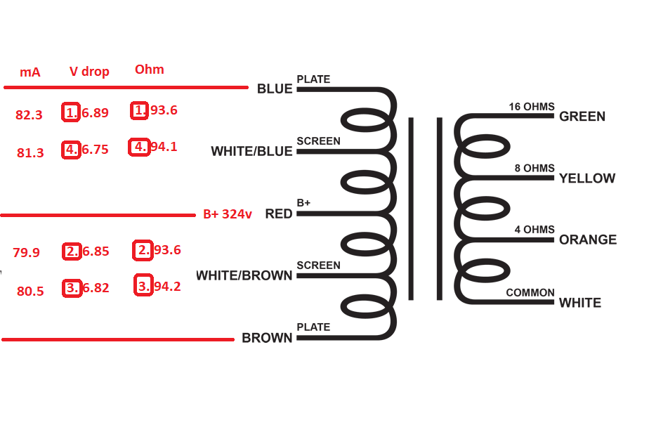
Here is all the voltage that I could get. The problem here is I don't have any information about the OT and PT. I was able to get the PT voltage and assume it's 400-500mA.
If 300B is at 324V, what should I set for negative bias?
Here is all the voltage that I could get. The problem here is I don't have any information about the OT and PT. I was able to get the PT voltage and assume it's 400-500mA.
You need a way to check the quiescent current balance in the output transformer windings.
Push current should match Pull current.
Your output transformers (and your ears) will love you.
Either put sense resistors in the 300B plates and set the bias for equal voltage drops;
Or measure the DCR of the push and pull windings and measure the volts drop of each 1/2 of the primary, and calculate: current 1 = voltage drop / push Ohms; current 2 = voltage drop / pull Ohms;
Or use separate filament supplies so you can measure the voltage of each independent sense resistor to ground.
The schematic provides individual bias adjustments, but no way to measure the resultant current of each 300B.
You should not switch the 12AX7 to a 12AU7 without changing several resistors on the board. The bias point of the two tubes are greatly different.
I am using 12AX7.
I don't know if my measurement is correct or not. What I did was remove the tube to measure the resistor current between B+ and Plate. Then inserted the tube to get the voltage drop. It doesn't seem right if I = V/R
So I took mA measurement from B+ to Plate as well which around 80+ mA
When bias -60v, the tubes temperature are around 185F, then I tried to adjust it down to -55v, then -50v, the sound is pretty much the same so I keep it at -50. The tubes temp at this point is around 170-175F. I really don't care much about the power since the room is 20'x20', just the sound quality. So may need around few watts. This amp design was 25w I think, but the wires they use in PT can't even get 400 for B+. With 296v or 310v, the B+ with voltage drop would get under 350v.
@-60v, B+ = 324v
@-50v, B+ = 283v, listen to few songs, can't tell the different yet.
- Home
- Amplifiers
- Tubes / Valves
- Need schematic for this 300B to improve