Hi stoolpigeon,
Could you reverse-engineer the digital/analog part of the dac board from dig. filter till I/V converters for as, thank you?
Could you reverse-engineer the digital/analog part of the dac board from dig. filter till I/V converters for as, thank you?
OK guys, I'd been wanting to do this for a while.
I cannot go any further tonight, sorry (maybe someone can do the homework on the datasheets, and maybe even put in Eagle?)
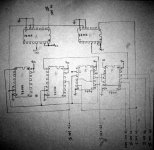
In case it wasn't readable:
Inputs (there's three, like the I2S lines, but I don't know yet which is which...) go to:
- pin2 of 7474
- pin 12 of 7474
- pin 1 of 7404
Outputs:
One line goes straight to all four DAC cards
Two other lines go individually to each DAC card (that I numbered in romans, I II III and IV); here too, I don't know which line is which signal.
Not in the drawing, the Vcc of each TTL chip is decoupled with 10nF to ground.
I'll do more "later on" (when will that be? can't promise...)
Hope this helps,
pilli
_
I cannot go any further tonight, sorry (maybe someone can do the homework on the datasheets, and maybe even put in Eagle?)
In case it wasn't readable:
Inputs (there's three, like the I2S lines, but I don't know yet which is which...) go to:
- pin2 of 7474
- pin 12 of 7474
- pin 1 of 7404
Outputs:
One line goes straight to all four DAC cards
Two other lines go individually to each DAC card (that I numbered in romans, I II III and IV); here too, I don't know which line is which signal.
Not in the drawing, the Vcc of each TTL chip is decoupled with 10nF to ground.
I'll do more "later on" (when will that be? can't promise...)
Hope this helps,
pilli
_
Attachments
...well, the output lines are easy t check, so they've been added in the picture below.
Another piece of info:
In the DAC cards, the TDA1541's receive the clock ("System Clock" at pin 4) from the I2S bit clock ("BCK" at pin 2). That is, pins 2 and 4 of the 1541 are connected together.
Now, for the input lines, those arrive from the rest of the player, which is "not easily reachable at this time of day".
Maybe someone can figure them out from the diagram already?
I am sure that they originate from an SAA7220, which means they are 4x oversampled.
The output I had posted earlier on in this thread.
That's pretty much it.
Who has time to put everything in Eagle?
goodnite, for now
(Edit: those letters A to F on the chips don't mean anything, just my reference to find the way while tracing...)
_
Attachments


...here we go with the corrections:
In the 7404 (marked "F" in my diagram)
a connection is missing from pin 2 to pin 3
and a connection is missing from "chipB-pin1" to "chipF-pin13".
(Now all the inverters have an input.)
And in the 74166 marked "C", pin 13 is connected to pin1 of "A", which also goes out to "DAC III Data".
(Now all the shift registers have an output.)
_
Hi pilli,
Thank you very much for schematic, I would really like to implement CA approach as I have few old, but in very good working order Philips/Marantz players as well as a dozen a TDA1541A doing nothing (all the same lot ;-) ...and I'm working in Eagle sch right now...
Thank you very much for schematic, I would really like to implement CA approach as I have few old, but in very good working order Philips/Marantz players as well as a dozen a TDA1541A doing nothing (all the same lot ;-) ...and I'm working in Eagle sch right now...
Hello everybody
Thank for the schematic Pilli.
Aparatusonitus can you post the Eagle schema wen you have done it ?
Thank a lot to all
Gaetan
Thank for the schematic Pilli.
Aparatusonitus can you post the Eagle schema wen you have done it ?
Thank a lot to all
Gaetan
Hello
Here is a web page about the CD3 modification, for those who would be interested;
http://www.lampizator.eu/LAMPIZATOR...3/Cambridge Audio CD3 CD player TDA1541A.html
Bye
Gaetan
Here is a web page about the CD3 modification, for those who would be interested;
http://www.lampizator.eu/LAMPIZATOR...3/Cambridge Audio CD3 CD player TDA1541A.html
Bye
Gaetan
Of course, but I would really like to see high resolution images of CA boards, you know, I don't want to mess something in layout.
Hello
Here is other CD3 photos there;
http://www.dcaudio.kgb.pl/cd3.htm
And CD2 (who are same but using cheaper laser and tda1541) ;
http://www.lampizator.eu/LAMPIZATOR/REFERENCES/Cambridge CD2/CD2 cambridge Audio CD player.html
Gaetan
Here is other CD3 photos there;
http://www.dcaudio.kgb.pl/cd3.htm
And CD2 (who are same but using cheaper laser and tda1541) ;
http://www.lampizator.eu/LAMPIZATOR/REFERENCES/Cambridge CD2/CD2 cambridge Audio CD player.html
Gaetan
Hi gaetan8888,
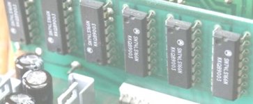
You are really fast...but I see at least 5 pc of SN74LS166N in the image, the last one on the left also look like it has SN74LS166N written on it...???
You are really fast...but I see at least 5 pc of SN74LS166N in the image, the last one on the left also look like it has SN74LS166N written on it...???
Hello
Since last week I was doing search about CD3.
Ok, I see which photo, yes there is 6 of those SN74LS166N
Gaetan
Since last week I was doing search about CD3.
Ok, I see which photo, yes there is 6 of those SN74LS166N
Gaetan
Very interesting.
So work's not finished yet.
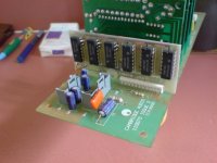
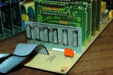
Now, what I have is actually not a "CD3" but a "DAC3". I always thought that the interiors were the same, but evidently they are not.
(This DAC3 is actually a strange bird, because Cambridge also made a DAC3 with a very similar box, but not quite the same, that had a double TDA1305 converter...)
Here's the picture of the card that I copied:
So work's not finished yet.
Now, what I have is actually not a "CD3" but a "DAC3". I always thought that the interiors were the same, but evidently they are not.
(This DAC3 is actually a strange bird, because Cambridge also made a DAC3 with a very similar box, but not quite the same, that had a double TDA1305 converter...)
Here's the picture of the card that I copied:
Attachments
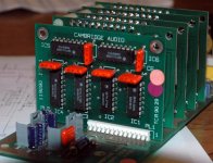
...I also have a CD2, whose TTL card is in this picture.
The chips are made unidentifiable, so I never really noticed that it is not the same layout as the DAC3. Six chips for six chips, right?
Except here they're all 16-pins, unlike the DAC3.
Now that I know that they are all 74166, I can try to trace them too.
_
The chips are made unidentifiable, so I never really noticed that it is not the same layout as the DAC3. Six chips for six chips, right?
Except here they're all 16-pins, unlike the DAC3.
Now that I know that they are all 74166, I can try to trace them too.
_
Attachments
I have also made a rough sketch of the processing before the dacs. I will tidy it up and post in the next few days.
sp
sp
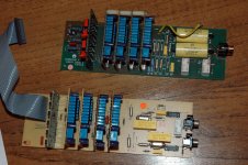
Here we see them side by side.
DAC3 is above, CD2 is below.
You can notice that implementation improved a lot.
Better output caps, relays both for mute and deemphasis (CD2 has a solid state "switch", a 4016, for deem), and of course (not visible) the CD2 has plain TDA1541's whereas the DAC3 has "1541A single crowns"
 with small heat radiators (glued on them
  ).
).
Then the DAC3 has LM317 power supplies, and the CD2 has 78/79xx, the DAC3 has the better SAA7220B.
There's not many traces of this family of players on the web.
Some time ago on eBay UK there was a so-called "Cambridge CD1" that was clearly the first implementation of this architecture. A massive two-chassis thing, where all the "secrets" were hidden (the shift registers thing). Now I regret not buying it, it's just that shipping stuff out of that island costs like building an underseas tunnel...
They made them better and better at each next edition.
I must say, the CD2 is this great design, implemented in a really cheap way: everything fries from too much heat, PCB has bypasses soldered all over, the 78/79xx thing, awkward Philips microcontrollers, that behave erratically (the well known display flickers)...
But man, what a sound!! Great, despite those "shortcuts". Never felt like modifying it.
The DAC3 is also kind of strange. I bought it with a "500T" transport (or something like that) also from Cmabridge, of which I never found any trace anywhere else. Looks like a CD3 without the DAC; if I remember well, it also has the SAA7220B, probably used just to put out SPDIF (I'll check downstairs later).
And the DAC3 has a Sony SPDIF receiver (in mine it is dead, so I feed I2S directly) and then the stuff I've been describing.
Long story to say that the CD2 sounds GREAT, and the DAC3 sounds INCREDIBLE. I thought it was the selected chips, but maybe the different "shifts" are also helping?
Anyway, I'm very glad that more fans of the Cambridge "quad-1541" architecture are around!!
I had seen the great site of Lampizator.
Personally, I wouldn't do that mod on these players: they do not have ANY output buffers to improve, and it's a pity to downscale to one converter only.
I did a tubes output stage on a more classical Philips machine, and that does sound great indeed. Didn't have time to compare with DAC3 yet (but then, he'd deserve a better I/V than 5334 for a fair comparison...)
_
DAC3 is above, CD2 is below.
You can notice that implementation improved a lot.
Better output caps, relays both for mute and deemphasis (CD2 has a solid state "switch", a 4016, for deem), and of course (not visible) the CD2 has plain TDA1541's whereas the DAC3 has "1541A single crowns"
with small heat radiators (glued on them ).Then the DAC3 has LM317 power supplies, and the CD2 has 78/79xx, the DAC3 has the better SAA7220B.
There's not many traces of this family of players on the web.
Some time ago on eBay UK there was a so-called "Cambridge CD1" that was clearly the first implementation of this architecture. A massive two-chassis thing, where all the "secrets" were hidden (the shift registers thing). Now I regret not buying it, it's just that shipping stuff out of that island costs like building an underseas tunnel...
They made them better and better at each next edition.
I must say, the CD2 is this great design, implemented in a really cheap way: everything fries from too much heat, PCB has bypasses soldered all over, the 78/79xx thing, awkward Philips microcontrollers, that behave erratically (the well known display flickers)...
But man, what a sound!! Great, despite those "shortcuts". Never felt like modifying it.
The DAC3 is also kind of strange. I bought it with a "500T" transport (or something like that) also from Cmabridge, of which I never found any trace anywhere else. Looks like a CD3 without the DAC; if I remember well, it also has the SAA7220B, probably used just to put out SPDIF (I'll check downstairs later).
And the DAC3 has a Sony SPDIF receiver (in mine it is dead, so I feed I2S directly) and then the stuff I've been describing.
Long story to say that the CD2 sounds GREAT, and the DAC3 sounds INCREDIBLE. I thought it was the selected chips, but maybe the different "shifts" are also helping?
Anyway, I'm very glad that more fans of the Cambridge "quad-1541" architecture are around!!
I had seen the great site of Lampizator.
Personally, I wouldn't do that mod on these players: they do not have ANY output buffers to improve, and it's a pity to downscale to one converter only.
I did a tubes output stage on a more classical Philips machine, and that does sound great indeed. Didn't have time to compare with DAC3 yet (but then, he'd deserve a better I/V than 5334 for a fair comparison...)
_
Attachments
pilli said:Long story to say that the CD2 sounds GREAT, and the DAC3 sounds INCREDIBLE. I thought it was the selected chips, but maybe the different "shifts" are also helping?
If that is the case, my vote goes to CA DAC3 TTL board + 4 x TDA1541A DAC boards to be copied...All I need is correct schematic and high resolution snap shots top and bottom for all cards😀
pilli said:Didn't have time to compare with DAC3 yet (but then, he'd deserve a better I/V than 5334 for a fair comparison...)
You bet, but we'll deal with that part latter...
Hello
I would do a tube passive I/V and output and low pass filter, like the Leicha Bogdanov DAC or the mr. Leach Adagio DAC. Or maby a cathode follower type. But no oversampling, so the filter would be done for the 4x analog shifted register upsampling. So it use a CS8412 or CS8414 receiver chip.
Gaetan
I would do a tube passive I/V and output and low pass filter, like the Leicha Bogdanov DAC or the mr. Leach Adagio DAC. Or maby a cathode follower type. But no oversampling, so the filter would be done for the 4x analog shifted register upsampling. So it use a CS8412 or CS8414 receiver chip.
Gaetan
Hi,
I'm done with Eagle schematic based on pilli's diagram from post # 23/24, now I would like to see how I2S lines from SAA7220 are connected to pin # 1 of SN74LS04N (IC1A) and pins # 2 & 12 of SN74LS74N (IC2A/B). I've used numbering of all components as in original board from image in post # 34. Also, this is good time to see how 14 pins connector is wired to TTL board as well as to all DAC boards. Now, I need a high resolution top and bottom image of the TTL and DAC boards as well as dimension of boards to produce exact copy (how inventing of me😀).
I'm done with Eagle schematic based on pilli's diagram from post # 23/24, now I would like to see how I2S lines from SAA7220 are connected to pin # 1 of SN74LS04N (IC1A) and pins # 2 & 12 of SN74LS74N (IC2A/B). I've used numbering of all components as in original board from image in post # 34. Also, this is good time to see how 14 pins connector is wired to TTL board as well as to all DAC boards. Now, I need a high resolution top and bottom image of the TTL and DAC boards as well as dimension of boards to produce exact copy (how inventing of me😀).
Attachments

- Status
- Not open for further replies.
- Home
- Source & Line
- Digital Source
- Need schematic for a Cambridge Audio CD3 cd Player