You should search DIYA for posts about symmetric IPS amps. The usual solution is to nix the current mirrors in favor of a resistor and most importantly, put a emitter degen resistor on the two VAS transistors. That could be by moving the VAS current limit resistors and transistors down from the upper cascode transistor to the lower VAS transistors. The current limit transistor collector would have to drive the first Darlington transistor.
The problem with a symmetric IPS is that the NPN and PNP LTPs always have a slightly different DC offset, so if the NPN LTP wants a higher DC offset than the PNP LTP, then the two VAS transistors are driven to a high current and if the NPN wants a lower offset then the two VAS are driven to zero current. You have two feedback loops that want (slightly) different results, so you need limits that are still usable operating conditions, ie limited DC gain.
I posted a bias servo idea in DIYA that measures the VAS current and biases both current mirrors, a common mode feedback that finds the desired VAS current automatically. I think Bob C has a circuit that adds some resistors to the current mirrors, along with VAS degen resistors, so that the current mirror voltage is somewhat defined. Search for "symmetric IPS".
The two-pole compensation is not exactly done my favorite way. I would return the resistors to the output and not to the supply rails. That gives a smother phase response and is less critical.
I would nix the voltage sense resistors on the output protection so that you have just a current limit, but that requires recalculation of resistor values.
As Hayk suggested, you should disconnect the FETs until you have a working stable amplifier unloaded. Then connect the FETS with a current limit on the supplies, ie the "light bulb" or large resistor kif you don't have a bench supply with current limiting. Shooting in the dark is a recipe for eternal failures.
You could also short the bias (VBE multiplier) until you get the VAS current under control, to prevent excessive driver current.
I'm not a huge fan of symmetric IPS because of the bias problems, and it does not provide much benefit, ie a single IPS can give PPM THD. And a symmetric design reduces even harmonics, which are desirable over odd harmonics. Instrument amps deliberately generate even harmonics.
Nuff 4 now.

See https://leachlegacy.ece.gatech.edu/lowtimI am new to this site. Do you have any link?
steveu posted the remedy: replace the current mirror load with a resistor and add emitter degeneration to the VAS. That will bring the gain down.
I agree with all of steveu's points except the last: I like the complementary IPS because it cancels bias currents, provides symmetrical +/- drive, and faults tend to result in zero output voltage. It is safer especially for DIY.
Ed
@mz543578854
The original design use 2SJ162 and 2SK1058. I replaced them with ECX10P20 and ECX10N20I cannot read the MOSFET types in the schematic above.
ok, my comments were too abbreviated, so i'll try again.The Amp is already built with much effort, it is not the time for lamentation but resolution. The fellow is asking help to make it function not opinion about his choice.
😉
elsewhere on this board is extensive discussion by others who have built this circuit (unsuccessfully) and folks with acknowledged expertise (such as Bob Cordell) on design changes needed to make a design of this topology work; otherwise it will not do so reliably. it is even possible one could unnecessarily damage expensive parts. not a pleasant experience in my opinion.
it would have been wise to review that info first, but that train has left the station...
so it would be prudent to review that info now to determine what fixes can be applied to the existing boards to increase the chances for this project to have a happy and successful conclusion, in addition to being more of an encouraging educational experience.
"i" think it is especially important to avoid the sour taste of frustrating failure for beginners and others interested in this hobby - we want more people to indulge and enjoy, not run away crying and screaming😢!
p.s. i just now see steveu's comments in post #21. read it closely! even for experts, it is difficult to simultaneously deal with trying to stabilize the design while troubleshooting its basic operation. negative feedback loops make it difficult to clearly isolate multiple problems so they can be resolved appropriately.
Last edited:
Well all these good comments need studying now... For my defense, I am a member of this site since a while but I didn't remember it. When I started this project and found this site while searching for an appropriate heat-sink, I was the first surprised to realize that my email was already existing at the time I tried to register on the site!
So yes I should have read more here before designing mine, but I didn't know the existence of this site yet. Well I kew it but didn't remember it. And I blindly read the book with a lot of confidence in it's author. Now I understand that this book is not as good as it look!
I though I had choose the best design... But I will not stop there ;-)
I also like the complementary input stage for improved power supply rejection (when I don't add extra rail treatments like regulators, cap multipliers, etc.)See https://leachlegacy.ece.gatech.edu/lowtim
steveu posted the remedy: replace the current mirror load with a resistor and add emitter degeneration to the VAS. That will bring the gain down.
I agree with all of steveu's points except the last: I like the complementary IPS because it cancels bias currents, provides symmetrical +/- drive, and faults tend to result in zero output voltage. It is safer especially for DIY.
Ed
@mz543578854 From where did you see the 1-star reviews... When I look back at the book reviews, it seem for me that the book is well quoted... From the screenshot below...I really hope you will not be getting discouraged from this great hobby and maybe even get this amp to function. Looking at the (1-star) Amazon reviews, I would not be too confident. They say what the knowledgable folks above say, uncontrolled bias etc. Many circuits in the book seem to be really bad.
I cannot read the MOSFET types in the schematic above. A MOSFET amp having exhaustively been discussed here in the forums pretty well suited for beginners is this: https://www.diyaudio.com/community/threads/power-amp-under-development.43331/
Maybe you can recycle enough components to not make this a too bad experience.
Attachments

it's not a "bad" book; the other projects in it are "safe". and who knows, maybe Slone was just testing the readers? 😈 i had lots of college engineering classes in which we were told wrong things on purpose or ordered to design and build something that couldn't be to test understanding and develop confidence in our abilities. or dealing with the lab techs who would miscalibrate scope probes or put the wrong parts in parts bin to trip you up if you didn't remember to check everything. painful at the time but good lessons in the long run!Well all these good comments need studying now... For my defense, I am a member of this site since a while but I didn't remember it. When I started this project and found this site while searching for an appropriate heat-sink, I was the first surprised to realize that my email was already existing at the time I tried to register on the site!
So yes I should have read more here before designing mine, but I didn't know the existence of this site yet. Well I kew it but didn't remember it. And I blindly read the book with a lot of confidence in it's author. Now I understand that this book is not as good as it look!
I though I had choose the best design... But I will not stop there ;-)
H
HAYK
You need first to bias the VAS. Apply 1k resistor across R104 39ohm and measure across R304 39ohm the voltage to be about 400mv by adjusting the value of the added resistor.
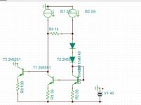
In order to resolve the undecided VAS standing current problem associated with Sloan's mirror-loaded, complementary push-pull LTP input-VAS stage, fellow member @chalky posted an approach a few years ago as attached and put it to a successful test. The idea is to force a standing current onto the VAS by mirroring a known, stable reference current into both the VAS transistors.

Apparently, in a real world build, the R1 that decides a 10mA reference current should be replaced with a quality constant current source circuit that is immune from the noise and fluctuation of the power rails.
The link to @chalky post is here
CurrentMirrorVAS
Apparently, in a real world build, the R1 that decides a 10mA reference current should be replaced with a quality constant current source circuit that is immune from the noise and fluctuation of the power rails.
The link to @chalky post is here
CurrentMirrorVAS
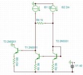
Another way to fix the undefined VAS idle current issue would be to connect resistors between Q1 and Q2 collectors and also Q3 and Q4 collectors. This would be easy to add to your assembly.
True. That measure was suggested by many. Bob Cordell also has a discussion in his book 👍, where he cautions its sensitivity to the LTP tail current balance between the PNP and NPN arms.Another way to fix the undefined VAS idle current issue would be to connect resistors between Q1 and Q2 collectors and also Q3 and Q4 collectors.
I actually used that circuit, with amendments, in one of my own 200W amps, with success. And that amp has been serving in my living room system 24/7 for more than 8 years non-stop.

In a nut shell, what the shunt resistors do is to establish a determined relationship between the VAS standing current and the LTP tail current. In the example in Bob's book , the VAS current is about 10x the LTP tail current, decided by the ratio (~20x) between the degeneration resistor values at the VAS and the input stage current mirror load.
However, in a real world build, one may not feel comfortable with ratios like 10x for a VAS current to follow at.
Back then in one brief simulation with LtSpice, by artificially changing one of the transistor parameters by about 20%, I found the VAS current would "re-settle" at 3-4mA apart from where it was before.
In my actual amp build, several measures were taken to address the possible aftermath.
-- The VAS stage was changed to Hawksford cascode that has a higher value degeneration resistance, hence reduced sensitivity. (upon prompt from @Dave Zan 👍)
-- In the PCB layout the LTP tail current sources have trimming resistor provision, for easily trimming out the LTP current imbalance if needed.
-- The Vbe multiplier bias current controller gets a bleeder transistor. It would allow the Vbe multiplier to work at about 4mA, anything excessive would be bypassed by the bleeder transistor. This would eliminate the possible output stage bias current hike on the VAS current drifting.
-- Using matched dual transistors in the input stage, the input diff-pairs, the cascode transistors, and the current mirrors.
this is the actual build Input-VAS
In the middle is an aluminum sheet metal heatsinking the cascode transistors to the VAS. To its right is the input stage.
If I were to try it again today I would most likely go with the current mirror VAS (two posts above) for its straightforward approach, no compromise to input stage mirror loading, no drifting, and a lot less other things to worry about.
H
HAYK
I did the simulation of adding resistor across the differential. Without resistor, I have 5ma, with 1ma. Adding a pair of diodes as Revox, 12.5ma.
Attachments
Yes, overall reviews look nice. Click on the left 1-star line to see the comments for 1-star ratings.@mz543578854 From where did you see the 1-star reviews... When I look back at the book reviews, it seem for me that the book is well quoted... From the screenshot below...
In general when looking at Amazon ratings, it always is a good idea to check bad ratings too. Of course also always take them with a grain of salt.
What I wrote is that the 1-star ratings exactly said what the knowledgable folks had replied in this thread.
Hello everyone's... I am back from a B77 MKII calibration for a friend... Yep..., I am a reVox fan! I have the B710, B750, B760, B790 and PR99, all recapped and calibrated by me...
I already read all goods comments above and I am ready to proceed with the necessary modifications to make my little project working. But first, I must say I really appreciate all schematics and parts references cited above but don't forget that this is my first amp project. So sometime when peoples are using shorts terms, like "LTP" for example, I may not know what you are meaning. It would be great if you at least put the whole words in parentheses (Like This) when you write the first occurrence of it in your explanations. But still, thanks for your efforts ;-) I am learning here...
@mz543578854, I did your trick for the 1-star link above... Man... Reading all those comments brought me down a bit. My mind though that the book was one of the best, and now my mind feel bluffed by the simple cover of a book. I know I should take them with a grain of salt like you mention but still...
@HAYK , after this post, I will proceed with your suggestion in post #30, and thanks again for taking the time to refer to my own schematic references, that help for sure... I'll post further here later...
@All, thanks everyone's for all your supports 🙂
P.S.: @r_merola... for the eyes only... ;-)
@HAYK, I did solder new resistors in parallel to R104 39 Ohms and measured the DC voltage across R304. The voltage seems to be constant at 57mV. I tried 1k Ohms, 100 Ohms, 39 Ohms and I am now at 10 Ohms in parralel for a resulting value of 8.1 Ohms at R104 but still the DC voltage across R304 is stuck at 57mV.
Should I understand to do the same on each mirror side, by means of R204 and R404 reciprocally?
Should I understand to do the same on each mirror side, by means of R204 and R404 reciprocally?
Ok... The more I read all suggested threads above, the more I see mention of Bob Cordell book. But now that I know the Amazon stars trick, I looked at the only one 1-star critical of this book ( beside all the positive ones). The guy who posted the critical say that you should better read the books from Self Douglas. I am reading Self Douglas book titled "Audio Power Amplifier Design" right now. I started it after having finish the one from G. Randy Slone, in the goal to better understand the amplifier designs. But I find it to much concentrated to the distortion issues. Although it is still very interesting, it's not exactly what I am looking for right now. And I should mention that most of the graph aren't compatible to my "Kindle Scribe" tablet reader. They are printed totally black on black and impossible to read. To the point where sometime I have to consult them onto my other Android tablet to see them. I did post these bugs via the tablet tools. Guess what? Amazon refund me the total amount of the book saying they were sorry but that the book is not compatible with my Kindle Scribe, but I can still read it. So to all of you who mentioned Bob Cordell book, could you confirm me that it would still be a valuable reading considering that I already have read all the books from my Kindle library below? Thanks in advance... (Although when I look at the price, I don't really see any reason not to buy it ;-) )
EDIT: Well, the book is not available in digital format here in Canada :-(

EDIT: Well, the book is not available in digital format here in Canada :-(
Last edited:
Yes, it is. The quick way to convince yourself is to thumb through it or review the table of contents as compared to that of the other books. Some authors push their own philosophies more; others try to give a more balanced approach. You just want good info you can trust and understand so you can learn to discern/decide what "you" want to have as design philosophies.
BTW, I don't know what your intent or your background is; if I make a guess, your reading stack looks to be missing some general electronics books. For example, "The Art of Electronics". Maybe you already have a deep electronics background and are just looking for the audio design elements?
BTW, I don't know what your intent or your background is; if I make a guess, your reading stack looks to be missing some general electronics books. For example, "The Art of Electronics". Maybe you already have a deep electronics background and are just looking for the audio design elements?
Last edited:
- Home
- Amplifiers
- Solid State
- Need helps! Weird signal results on my DIY High-performance Hyrid MOSFET Audio Power Amplifier