Unable to do so - There was a very brief loud hum and a blown fuse.
...
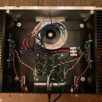
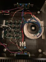
OK, everything up to the rectifiers (both measure 16.8VDC) checks out, but when the board is connected fuses blow.
Am I wrong or would that point to the board at this point?
Yeah... that's not right.
Ok, one last thing to try... remove the thermistors and see if you still get the hum and blown fuse.
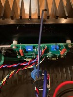
The correctly matched blue/green wires are zipped tied together.In the interest of being very thorough can we verify that the correct blue/green wires are going to each rectifier?
Measured OL btween both blues.Also use your meter to make sure there is no resistance between the two blues which would indicate a transformer defect.
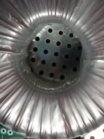
I measured both blues to the chassis. One was OL and the other was.......wait, what?.......0.7 ohms!Also, use your meter to make sure there is infinite resistance from each blue wire to the chassis. No shorting of the transformer to the chassis.
I flipped the transformer over and saw a small break with a wire exposed.
That can't be good.
Attachments

I've been watching this thread and learning a LOT! So many wonderful minds helping with troubleshooting! Fantastic to see the issue was found. Hip hip hooray!
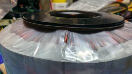
I got an AS-2218 for mine but haven't wired it up yet. While looking at it yesterday I noticed something similar. Luckily the bottom seems fine and it's just this one winding on top. This is going to make me be extra cautious with transformers now.
Attachments
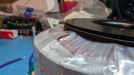
I got an AS-2218 for mine but haven't wired it up yet. While looking at it yesterday I noticed something similar. Luckily the bottom seems fine and it's just this one winding on top. This is going to make me be extra cautious with transformers now.
I had only one mounting washer which I put on top. Tomorrow, I am going down to my hardware store and buy a rubber mat to put under my transformer. If you have stock in fuse manufacturers I recommend you sell immediately.Were you using the rubber mounting washer?
I'll share this 3D printed solution if anyone else wants to give it a try. If you don't have access to a 3D printer, I'm willing to provide parts. I have full kits of the vertical mount ($5 + shipping) per kit [that's less than my cost by some change]. The horizontal mount I'm willing to give away for free if shipping is covered. Just sharing as both options avoid the shorting issue that was found. Another cheap option is the L-bracket approach, but that may not work in a 3U chassis.

I will be donating a number of the vertical kits above to the raffle at Burning Amp Festival this year. They work with Antek 200, 300, and 400 VA AS and AN transformers.
As of 10/11/24 I have 3 transformer seats available to give away. I will update this post as they are snagged up. I'm offering up a free 3D printed seat for interested persons as long as shipping label is sent to me. 2 quantity limit per person please. Works with both 300VA and 400VA Antek transformers (or similar dimensions).
I can ship these to anyone interested as long as you pay for shipping by sending me a shipping label. To make it slightly more enticing, I'll also include a few other fun 3D printed parts you can use in builds in the shipment. Please PM me for details on how to...
I can ship these to anyone interested as long as you pay for shipping by sending me a shipping label. To make it slightly more enticing, I'll also include a few other fun 3D printed parts you can use in builds in the shipment. Please PM me for details on how to...
UPDATE NOTE: If you want to use an Antek 400VA transformer with this seat, you do need to use some 10-15mm spacers for the 130mm pipe strap. The slightly larger diameter of the 400VA over the 300VA transformer means there's a gap that exists between the chassis perforated plate and the strap ends. If you don't care what it looks like, then spacers really aren't needed as they don't increase the strength of the "grip". You do need to use longer M4 bolts (M4 10-12mm work for a 300VA, but 20-25mm are needed for 400VA. The spacers just make a cleaner look is all by flattening the tabs (see...
I will be donating a number of the vertical kits above to the raffle at Burning Amp Festival this year. They work with Antek 200, 300, and 400 VA AS and AN transformers.
Okay, so there WAS voltage on the chassis 😱The correctly matched blue/green wires are zipped tied together.
Measured OL btween both blues.
I measured both blues to the chassis. One was OL and the other was.......wait, what?.......0.7 ohms!
I flipped the transformer over and saw a small break with a wire exposed.
That can't be good.
Luckily nothing more happened!
That's a great "lesson learned" for all of us about the importance of transformer mounting and always having a thick rubber barrier to guard against a short circuit like that. Good stuff and another one for the mental notebook...the other was.......wait, what?.......0.7 ohms!
I flipped the transformer over and saw a small break with a wire exposed.
I cannot count the number of times (and it continues to this day) I've benefited from the kindness and knowledge of my fellow forum members. It was a good feeling to be able to help pay some of that back.
Regards,
Dan
Regards,
Dan
Hi Guys,
It's official. After taking the weekend of I cut a rubber mat under the transformer and taped up the bare wire, I hooked the PS, held my breath and turned on the power. And nothing happened. No loud hum, no blown fuse, just 49.5 watts at the rails.
I want to express my sincere gratitude for your generous time and advice. You guys really whipped me into shape for troubleshooting. You had me checking things I never would have thought of, assuring me it was only a matter of time when started feeling a bit discouraged. It's fantastic that the community would rally around an amateur with rudimentary troubleshooting skills. It speaks volumes about you.
Tomorrow I am going to wire the PS to the amp boards, put on some music and hear the fat lady sing.
Thanks,
Dave Chorney
Hi All,
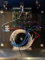
I'm going to piggy back on this one as I also need help with a F5m build. I tested the power supply, everything seemed good, powered down, came back today. Hooked up the channels, turned the potentiometers, powered up, smoke on one channel through R6&R7. The power supply is putting out ~26V each side. Maybe I should be using dual rectifier bridges? I don't understand why the short wouldn't be symmetrical. Anyway, should I be starting over or is there a way to salvage the boards?
I'm going to piggy back on this one as I also need help with a F5m build. I tested the power supply, everything seemed good, powered down, came back today. Hooked up the channels, turned the potentiometers, powered up, smoke on one channel through R6&R7. The power supply is putting out ~26V each side. Maybe I should be using dual rectifier bridges? I don't understand why the short wouldn't be symmetrical. Anyway, should I be starting over or is there a way to salvage the boards?
Attachments
Check the case of the mosfet to ground. After that, pull the mosfet off and look for discoloration on the mating surface of the mosfet.
I assume for the secondaries, you have
AC1 to one side of the bridge
AC2 to gnd
AC3 to gnd
AC4 to the other side of the bridge?
I assume for the secondaries, you have
AC1 to one side of the bridge
AC2 to gnd
AC3 to gnd
AC4 to the other side of the bridge?
........ I tested the power supply, everything seemed good, powered down, came back today. Hooked up the channels, turned the potentiometers, powered up, smoke on one channel through R6&R7. The power supply is putting out ~26V each side. .............
When you tested the power supply, did you measure +26V between V+ and Ground and -26V between V- and Ground?
Looking at your second picture I see that the right channel is not connected to the power supply and the left channel appears to be only partially connected to the power supply. Was this the wiring when you powered up?
The V+ out of the PS should be connected to V+ on the amplifier board, V- out of the PS should be connected to V- on the amplifier board, and G out of the PS should be connected to G on the amplifier board.
Very important: did you turn both pots fully counterclockwise before powering up?
The mosfets don't look discolored but I'll take a closer look at the back.
On the bridge, the positive from the board (red wire) goes to the positive on the bridge. Negative from the board (blue wire) kitty corner.
Yes, ~26V - positive and negative both sides.
Sorry, that picture was in-process (updated attached). Everything was soldered and aligned prior to power up - green ground, white negative, yellow positive.
Pots were turned fully prior to power up but after connecting to power supply.
Attachments
Check the amplifier pcb for correct parts at all locations. Check that Q3 is IRFP9140 and Q4 is IRFP140.
- Home
- Amplifiers
- Pass Labs
- Need Help with F5M Build