Unfortunately I couldn't clearly see the wiring of the IEC connector. But if you are getting the correct secondary voltages that is good. You can also check for accidental shorts there by making sure the AC is unplugged from the wall. Then set your multimeter to resistance and check the resistance of the IEC neutral AC to chassis ground. Then check the resistance of the IEC hot AC to chassis ground. They should be very high resistance. Also check IEC safety ground to chassis safety ground, which should measure very low resistance.
All these simple checks are to make sure everything is correct, starting at the IEC. You have written that the transformer secondaries are confirmed to be correct. The next step is to connect the secondaries to the rectifiers (PS board not connected) and confirm that the output of the rectifiers are correct.
Then the next step is to examine and check the PS board as I had previously mentioned.
The strategy is to start at the AC input and work step by step through the power supply until the problem is found.
Looking at your pictures, the PS board looked very close to the chassis bottom plate. How much of a gap do you have between the bottom of the PS board and chassis bottom plate? Hopefully no part of the PS board or its components' leads are touching the chassis bottom plate.
Last edited:
Post a picture of the bottom of the PS board. Check that the wiring is correct. Also check that the board and components are not touching the chassis and shorting the power supply to ground.
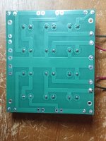
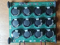
Here is the PS board, bottom and top. I don't see any problems with the soldering and the top view shows the capacitors oriented correctly. At the top of the top view, you can see that the ground thermistor cracked while I removed the board. I'm going to replace this thermistor ASAP.
The thermistor to ground that glowed indicated that somehow current was flowing from the PS board ground through the thermistor to chassis safety ground. So that path needs to be found and corrected before powering up.
That's the $64 question. How would I look for that short/path? I believe I have eliminated any possible problems from the IEC to the board, unless you see something I didn't (in which case, feel free to berate me). That would seem to leave the board. I would be grateful for any suggestion where the problem might be.
Attachments
Here is something I just don't get. From the Pass page:
I see inscriptions for jumpers on the board. I have no idea how I would use or not use this or if this part of the problem.Note also that there are provisions for jumpers between the two channels V+ and V- to allow them to operate in parallel for monoblock operation.
You, Ben, and I can easily go through this step by step by step and verify everything. From the posted conversation so far everything up to and including the rectifiers appears to be correct (assuming you have the blue/green pairs correct). I'm with Ben on some sort of short on your PS board. A bad capacitor? Doesn't appear to be any capacitors installed incorrectly. PS board touching the chassis? It's always something simple.
Regards,
Dan
P.S. I'm willing to keep going until this is fixed!
Regards,
Dan
P.S. I'm willing to keep going until this is fixed!

Well, the next step as I had mentioned is to test for DC voltage out of the rectifiers.
The jumpers, whether in or out, should not cause the problem that you have noted.
One way for DC to be present in the ground of the bipolar supply is have either the V+ side or the V- side of the supply to be accidentally grounded.
Looking at your pictures, I see the chassis grounding screw connecting the IEC safety ground wire to the chassis is very close to the V+ input on the PS board. Was that screw touching the board? It is best to reposition it away from the board.
Yup, correct and 'identical' DC output from both rectifiers when not connected to the PS board.
Regards,
Dan
Regards,
Dan
Try a different outlet on a different breaker branch. Maybe something on this branch is pulling the neutral away from the safety ground, and some other appliance is using your amp as a return. Although I'm not seeing how the path gets completed from the secondary side ground back to primary neutral. Still, doesn't cost anything to check the relationships of all three prongs at the outlet.
Last edited:
That's what I'm betting my two cents on.I wonder if there’s a shorted capacitor…
I wonder if there’s a shorted capacitor…
That would send DC to ground. If everything else checks out, that would be something to check.
That’s the thing… I’m looking at these photos with a magnifying glass and can’t see anything wrong. I suspect we’re at the point where it’s not visually obvious.
That seems to be the simplest explanation at this point.I wonder if there’s a shorted capacitor…
The solder joints look nice. No splatter. So any short would have to be on the top side. It would be a shame to have to unsolder all those caps to find a short. Maybe cut traces, and then bridge later when done? Still ugly, so maybe unsoldering is the better coice. You can definitely narrow it down to one of the two secondaries by unplugging at the diode bridges before starting on the caps.Here is the PS board, bottom and top. I don't see any problems with the soldering and the top view shows the capacitors oriented correctly. At the top of the top view, you can see that the ground thermistor cracked while I removed the board. I'm going to replace this thermistor ASAP.
That's the $64 question. How would I look for that short/path? I believe I have eliminated any possible problems from the IEC to the board, unless you see something I didn't (in which case, feel free to berate me). That would seem to leave the board. I would be grateful for any suggestion where the problem might be.
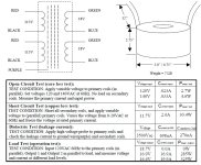
What's up with your secondary windings? I find it highly unusual that windings have mixed color wires, usually one winding will have one color. Could it be that one secondary is actually green/green and the other is blue/blue?
Hi, one thing isn't clear; you wrote that the thermistor at the power inlet got hot and cracked. But one of your pictures shows a cracked thermistor at the output of the psu (the ground lifting one), which isn't the power inlet, while the one at the AC inlet is intact. Could you please clarify this?Thermistor at power inlet got hot and cracked. I haven't turned on unit since but just got a new thermistor,
- Home
- Amplifiers
- Pass Labs
- Need Help with F5M Build