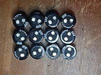
I desoldered the caps and tested them by the following procedure:
The results I got were pretty consistent. I measured between 1.856 and 1.999 (Step 4) before my meter showed "OL" on all caps (Step5).
It would seem that all caps test good according to this test. I tested each cap twice.
- Make sure the capacitor is fully discharged.
- Set the meter on the Ohmic range (Set it at least on 1000 Ohm = 1kΩ).
- Connect the multimeter probes to the capacitor terminals (Negative to Negative and Positive to Positive).
- Digital multimeter will show some numbers for a second. Note the reading.
- And then immediately it will return to the OL (Open Line) or infinity “∞”. Every attempt of Step 2 will show the same result as shown in steps 4 and 5. It means that Capacitor is in Good Condition.
- If there is no Change, then Capacitor is dead
The results I got were pretty consistent. I measured between 1.856 and 1.999 (Step 4) before my meter showed "OL" on all caps (Step5).
It would seem that all caps test good according to this test. I tested each cap twice.
Attachments
Fine. Could you please make pictures from your now empty pcb, from both sides? So we can check if it has some issues (what I don't think).
Further, could you tell where the cracked ground lifter thermistor was connected - one side on the pcb gnd, but the other side?
Also measure the voltage on the rectifiers + and -.
Further, could you tell where the cracked ground lifter thermistor was connected - one side on the pcb gnd, but the other side?
Also measure the voltage on the rectifiers + and -.
Looking at your pictures, the PS board looked very close to the chassis bottom plate. How much of a gap do you have between the bottom of the PS board and chassis bottom plate? Hopefully no part of the PS board or its components' leads are touching the chassis bottom plate.
Looking at your pictures, I see the chassis grounding screw connecting the IEC safety ground wire to the chassis is very close to the V+ input on the PS board. Was that screw touching the board? It is best to reposition it away from the board.
I had mentioned the above as items to check. They may or may not be issues but they can only be checked in person by digititis as I only have the provided pictures to view and I cannot tell one way or another.
I had also asked for voltage checking at the DC output of the bridge rectifiers previously but I have not seen a reply.

I took a look again at your pictures and there seems to be a bare cable going under the base plate - what is this cable, where it is going? Also, it seems to be a cable (but barely visible) going under the base plate just "above" the pcb.


Okay, the other side of the thermistor goes via screw directly to the chassis, so this question is answered.
To crack the thermistor you need voltage between the gnd of the psu and the chassis. If the caps are fine (and the rectifiers too), you must have voltage on the chassis.
To crack the thermistor you need voltage between the gnd of the psu and the chassis. If the caps are fine (and the rectifiers too), you must have voltage on the chassis.
Last edited:
The one thing we 'know' for sure is that there was probably 10-15 amps flowing through the one thermistor to ground. The community at large has tried to make sure that everything is wired correctly. It appears that the primary side of the toroid transfomer has no obvious wiring errors. It has been suggested that that Dave make sure that the correct (blue/Green) secondary wires are going to each rectifier. This appears to be correct. Referring to the below drawing we see four points (A,B,C,D) that we can disconnect to be able to measure the output of the rectifiers. I'd have to reread the thread to see if this has been down and posted. One extra step I would probably do, because I have lots of extra stuff lying around, is just put a 1K or so resistor across the outputs of the rectifiers to see if I can draw 20mA or so without anything silly happening. If that all checks out the consensus is that the issue has to lie somewhere on or something to do with the PS board. Since it's unlikely the board is defective so we continue our search for defective components. Capacitors initially check out so we have to check the remaining thermistors and agree on a method to verify there's no shorts on the board. After that we'll take a step back and form a plan to find this issue. The answer is looking at us. We just have to see it? 😉
Regards,
Dan

Regards,
Dan
I haven't seen this step posted and it strikes me as excellent advice.I suggest disconnecting the transformer secondaries from the rectifiers and use a meter to confirm the pairing of the blue and green are correct for each secondary. Check each pair for resistance (continuity).
Then connect them back to the rectifiers. Disconnect the DC wires from the rectifiers and power up to confirm the DC voltage from the rectifiers.
If all are correct, then connect the DC to the PS boards and test. First test without the thermistor connected to ground.
A Dim Bulb Tester would be handy for power-up testing.
Regards,
Dan
While you are at it, you might as well check the primary-secondary isolation and measure the primary DC resistance.
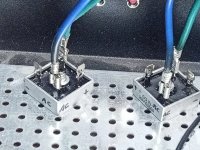
I tested both rectifiers and got the same for each which is 16.8V. I marked each corner to idiot-proof their orientation.I had also asked for voltage checking at the DC output of the bridge rectifiers previously but I have not seen a reply.
The PCB board is .25" avove the chassis bottom plate and makes no contact.Looking at your pictures, the PS board looked very close to the chassis bottom plate. How much of a gap do you have between the bottom of the PS board and chassis bottom plate?
The loose wire is connected to an amp board and will connect to the PS when I get this sorted. It sometimes gets in the way in my pictures.I took a look again at your pictures and there seems to be a bare cable going under the base plate - what is this cable, where it is going?
Wasn't touching but will move.Looking at your pictures, I see the chassis grounding screw connecting the IEC safety ground wire to the chassis is very close to the V+ input on the PS board. Was that screw touching the board? It is best to reposition it away from the board.
The ground lifter thermistor is properly connected here. I makes contact with the chassis through the standoff right next to it, so if you see the standoff there it is grounded.Further, could you tell where the cracked ground lifter thermistor was connected - one side on the pcb gnd, but the other side?
Attachments
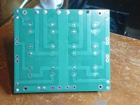
While the PCB is already empty, why not check the different nets for proper isolation from each other. That way we can exclude a problem with the board itself.
Should I do this without the caps? I haven't resoldered them in yet.If all are correct, then connect the DC to the PS boards and test. First test without the thermistor connected to ground.
Should I do this without the caps? I haven't resoldered them in yet.
1/4" standoff height is too low, with no margin for error. I suggest 1/2" minimum.
Since you have the caps off, yes, connect the PS board to the rectifiers and measure V+ to Ground and V- to Ground. Do that first without the thermistor to Ground, and with the PS board not connected to the chassis., and if successful, then mount the board to the chassis and test again.
If successful, add the thermistor to Ground and test again.
Unable to do so - There was a very brief loud hum and a blown fuse.Since you have the caps off, yes, connect the PS board to the rectifiers and measure V+ to Ground and V- to Ground. Do that first without the thermistor to Ground, and with the PS board not connected to the chassis., and if successful, then mount the board to the chassis and test again.
They range from 10 ohms to 12.8 ohms.Can you check the 4 rail thermistors with an ohmmeter?
OK, everything up to the rectifiers (both measure 16.8VDC) checks out, but when the board is connected fuses blow.
Am I wrong or would that point to the board at this point? It seems we are out of other possibilities.
Unable to do so - There was a brief loud hum and a blown fuse.Since you have the caps off, yes, connect the PS board to the rectifiers and measure V+ to Ground and V- to Ground. Do that first without the thermistor to Ground, and with the PS board not connected to the chassis., and if successful, then mount the board to the chassis and test again.
In the interest of being very thorough can we verify that the correct blue/green wires are going to each rectifier? This means disconnecting the blue/green wire from each rectifier and measuring the resistance between the blue and green. I'm guessing you'll get a couple ohms? Also use your meter to make sure there is no resistance between the two blues which would indicate a transformer defect. Also, use your meter to make sure there is infinite resistance from each blue wire to the chassis. No shorting of the transformer to the chassis.
And, we not are out of possibilities. We just haven't found the problem yet. We will.
Regards,
Dan
And, we not are out of possibilities. We just haven't found the problem yet. We will.
Regards,
Dan
I am not sure what you mean. I have very limited experience troubleshooting.While the PCB is already empty, why not check the different nets for proper isolation from each other. That way we can exclude a problem with the board itself.
- Home
- Amplifiers
- Pass Labs
- Need Help with F5M Build