Many thanks - actually it looks a lot easier than using the D flip flop but I will try both.
Are they 1 uf caps by any chance and which diode value is required - can't be much - any diode OK ? 1N400....
Andrew
I am using a 7HC4040 (not a 74hc04 which is a hex inverter) which is a binary ripple divider that has 12 outputs, each one half the frequency of the preceeding one. Ie it can divide by 2,4,8,16 etc.
So by connecting a 6 way dip switch to 6 of the outputs I can choose the divider output for whatever clock input I use. eg for NOS, bck = 2.8Mhz so by selecting the divide by 8 output, gives a dem clock of 350Khz
So bck or a divided version of it goes to pins 2 and 3 (the inputs of one gate of the 74HC02, pin 1 being the output) or in my case, a74HC14 schmitt input inverter. (The others are used along with a 74HC02 to 'split' the I2S into separate left and right data streams for feeding to each dac in my dual differential set up.)
I have read and re read all the replies I've had to some of my inane questions and have decided to quit while I'm behind - I usually quit when I'm ahead !
I know what I want to do but do not have sufficient grasp of the technicalities behind it. Neither do I understand the workings of my machine sufficiently to enable me ask the right questions nor complete the task the way some of you have.
So I'm going for the attached - whose design I think belongs to ecdesigns.
I am sure I can implement this and have most of the bits to complete.
If this IS actually DEM re clocking then I will be DEM re clocked in a few days.
The nice thing is however - if I completely blow up my dedicated / separate DAC board it will be the spare one - not the one I've moderately modded and listen to daily.
I apologise for my ineptitude on the subject but will let you know how I get on - no further questions - I promise....😱
Andrew
Attachments

So I'm going for the attached - whose design I think belongs to ecdesigns.
I am sure I can implement this and have most of the bits to complete.
If this IS actually DEM re clocking then I will be DEM re clocked in a few days.
Andrew, the one you attached is the Grundig design
Andrew,
Well, you have two more choices apart from quitting... So:
1) Read up, educate yourself and return to the whole subject in a few weeks.
2) See if there is someone near you who has more experience and understanding
30 Quit while you are behind...
Ciao T
I have read and re read all the replies I've had to some of my inane questions and have decided to quit while I'm behind - I usually quit when I'm ahead !
Well, you have two more choices apart from quitting... So:
1) Read up, educate yourself and return to the whole subject in a few weeks.
2) See if there is someone near you who has more experience and understanding
30 Quit while you are behind...
Ciao T
Thanks Thorsten
I see ' quit ' at number 30 ! - I'll do that then🙂
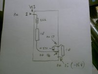
Grundig way seems easy to do and if I can't put a resistor and a cap from pin 1 to pin 16, put a cap between pin 15 and 17 and finally place a diode between 16 and 17 by now then I must concentrate on speakers, gardening or stamp collecting. I have done more complicated things than this.
Hope it works.
Thanks for everyone's help
Andrew
I see ' quit ' at number 30 ! - I'll do that then🙂
Grundig way seems easy to do and if I can't put a resistor and a cap from pin 1 to pin 16, put a cap between pin 15 and 17 and finally place a diode between 16 and 17 by now then I must concentrate on speakers, gardening or stamp collecting. I have done more complicated things than this.
Hope it works.
Thanks for everyone's help
Andrew

I just read the datasheet for the TDA1541 and it says pins 16 and 17 are N/C is that right? so it seem I can't use DEM reclocking, does to SQ of the the TDA1541 differ that much from the TDA1541A?
I bought one of the TDA1541A chips form china for $5 do you think its a fake, because its so cheap?
Does the DEM reclocking from the Grundig circuit work as good as the one with the 74HC02. How does it work exactly why would it take the signal from WS and not BCK like the other circuit?
I bought one of the TDA1541A chips form china for $5 do you think its a fake, because its so cheap?
Does the DEM reclocking from the Grundig circuit work as good as the one with the 74HC02. How does it work exactly why would it take the signal from WS and not BCK like the other circuit?
I just read the datasheet for the TDA1541 and it says pins 16 and 17 are N/C is that right? so it seem I can't use DEM reclocking, does to SQ of the the TDA1541 differ that much from the TDA1541A?
I bought one of the TDA1541A chips form china for $5 do you think its a fake, because its so cheap?
Does the DEM reclocking from the Grundig circuit work as good as the one with the 74HC02. How does it work exactly why would it take the signal from WS and not BCK like the other circuit?
Some TDA1541s have de cap on chip. All confusion is to blame Philips and their lousy data sheets.
You can easily check if it's present by running the DAC with a -60dB low level sine signal without the cap attached at pin # 16-17. If it's missing and not built in you will see gross crossover like distortion on your scope.
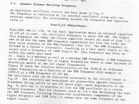
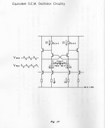
Attached some info from Philips on DEM
The diode is clearly a 6.2V zener diode.
Attachments

Last edited:
You can check the date on the chip.
I think anything into year 2000 + and it won't be real.
Someone else may be able to tell you when they stopped production.
The number at the bottom of the chip will say something like :
HSH8749 2 Y - ( this is one of my chips ) it means it was made during the 49 th week of 87......8749
That is cheap though - good luck with it
Interesting that distortion seems to appear from 250KHz, while good results have been achieved up to 2.8Mhz...
Interesting that distortion seems to appear from 250KHz, while good results have been achieved up to 2.8Mhz...
Yup
Attachments
My Chip says this
TDA1541 R1
4212
HSH8731 5 Y
what is the best dem clock frequency and where do i get it from
TDA1541 R1
4212
HSH8731 5 Y
what is the best dem clock frequency and where do i get it from
My Chip says this
TDA1541 R1
4212
HSH8731 5 Y
what is the best dem clock frequency and where do i get it from
Your R1 was made in the 31st week of 1987 according to the numbers so it may well be OK.
I've gone for 352.8 khz using a 250pf capacitor on pins 16 and 17 and it was good. That is not DEM reclocking of course but a simple mod to improve jitter performance by using better value cap across the DEM pins.
It was this mod that made me want to go further and do the job properly. At this point in time I do not fully understand it. I can tell you I will be doing DEM as per the attachments I posted earlier - it's easy enough if you take a look at it - I just want the clever guys to tell me it will be OK and better than standard.
If you watch - someone will tell me soon then you can do it too 😀
Andrew
My Chip says this
TDA1541 R1
4212
HSH8731 5 Y
what is the best dem clock frequency and where do i get it from
PM sent - check your messages
What is the frequency from the WS pin on the TDA1541 on a NOS DAC with CS8412 16-Bit 44Khz
Last edited:
What is the frequency from the WS pin on the TDA1541 on a NOS DAC with CS8412 16-Bit 44Khz
Its 44.1k because its the left/right select signal, so as there are 44.1K samples per second per channel and this includes both left and right channels, then it has to be the same.
i.e. when ws is low the left channel data is present on the data input (pin3) and when its high the right channel data is being transmitted to pin 3.
You can work out the bit rate in similar fashion - its 44.1kHz sample rate * 2channels * 16bits = 1.411Mhz (from the CS8414, so before any oversampling)
Some people say that the TDA1541 sounds the best at 352.8Khz how would you get that frequency from the BCK Pin.
BCK (1.412MHz) -> divide freq. (325.8KHz) -> Grundig DEM Clock Circuit
BCK (1.412MHz) -> divide freq. (325.8KHz) -> Grundig DEM Clock Circuit
Some people say that the TDA1541 sounds the best at 352.8Khz how would you get that frequency from the BCK Pin.
BCK (1.412MHz) -> divide freq. (325.8KHz) -> Grundig DEM Clock Circuit
Common, get your brain into gear!
What is 1.412Mhz divided by 352Khz its 4!
And no you can't divide by 4 with a 74hc4020, you'll need a 4040.
- Status
- Not open for further replies.
- Home
- Source & Line
- Digital Source
- Need help with Analogmetric TDA1541 DAC