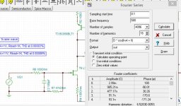
Transferred it to TINA-TI sim
THD at 0.00043%
I like this one a lot
J113 gives the lowest THD at 0.00037
THD at 0.00043%
I like this one a lot
J113 gives the lowest THD at 0.00037
Attachments
Last edited:

Where did you get LS844 spice model? I searched everywhere and cannot seem to find it. I want to plug it to see distortion sim data. ThanksIf you want very low noise and very high input impedance
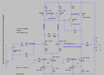
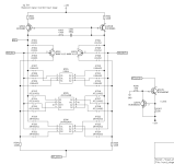
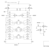
then add a discrete Fet input. To increase bandwidth, can use a cascode.
To reduce noise even further we can lower the voltage to
the Fet using a Cascode referenced at 7 volts.
While the opamp has full output to 600 ohms at 30 volts.
Another benefit is making it driven cascode which adds a additional
feedback with R9. additional feedback and extremely low noise
brings distortion even lower to .0002 %
View attachment 1174646
View attachment 1174648
LS844 gives the worst results for THD:
0.00076%, A=1V, 1kHz, Rload=1K
0.0010, A=11V, 1kHz, Rload=1K
Probably sounds better than J112 or 2N7002... excited to hear once I make physical board
0.00076%, A=1V, 1kHz, Rload=1K
0.0010, A=11V, 1kHz, Rload=1K
Probably sounds better than J112 or 2N7002... excited to hear once I make physical board
Last edited:
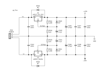
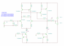
Updated schematics for the board to include CCS for FETs. Added decoupling caps. Added jumpers to GND for the input stage.
Should I add trim for CCSs to be able to play with current value?
Should I add trim for CCSs to be able to play with current value?
Attachments
I attached a PDF produced by InterFet in 2019Where did you get LS844 spice model? I searched everywhere and cannot seem to find it. I want to plug it to see distortion sim data. Thanks
containing hundreds of standard FET models and Linear Systems FET
Likewise the TINA-TI library in the software includes a rather good collection
of standard FET devices.
And include available temperature analysis if needed.
I usually test small signal devices 20 to 25c than power devices 27 to 65c
or higher if testing thermal tracking circuits.
Attachments
Last edited:
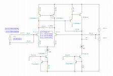
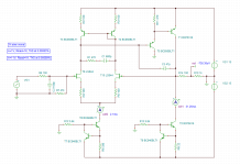
Other argue that the current should be 30mA. Which one is correct, 30 or 60? Is it because class A efficiency is 50% and so the current needs to double from 15V/600R is 25mA?Real life it will still want 60 to 70ma to get good swing.
Its class A output so current is massive.
Since ideal current source in model is beautiful impedance
I can weasel good swing with 25ma.
I tested with internal resistance
and simple current source. still manages .003%
could probably try feedback current source.
I just nailed it open with Zener for 58 ma
View attachment 1173793
I like the name for attachment , “source follower madness” 😂followers can be fun.
Some of the Fet packages you mentioned.
Especially the new Dual package that Texas Instruments released
Would be fun for some Fet follower.
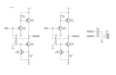
I tried a design with additional diamond buffer with the 600 ohm thing.
View attachment 1173922
Last edited:
Previously I have made a few PCB layouts using LM4562 as a voltage followers for my balanced power amplifier, but now I want to do a voltage follower having only discrete elements.
I am not sure if I want to do "evaluation" PCB with bunch of jumpers to be able to switch between 4 different JFETs. Seems too cumbersome.
I am still thinking about schematics and playing with different versions in the simulator. I was able to find and to load all of the SMD components' models into TINA-TI and LTSpice and I am attaching what I think is my PCB layout will look like.
Any mistakes I need to fix?
Thank you everyone for help 🙂
PS
Another idea I had was to make a JFET tube sound simulating circuit where I would just have 2nd harmonics distortion of say 0.01% for 1kHz.
Attachments
H
HAYK
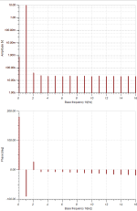
When measuring Fourier analysis with Tina, you must give a certain time before starting analysis to get correct answer. If you analyse the distortion of a RC lowpass without start time you will read lot of wrong measured distortion. When you apply more than 1ms, Tina will not accept, do not give any attention.
Attachments
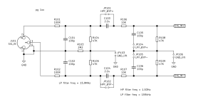
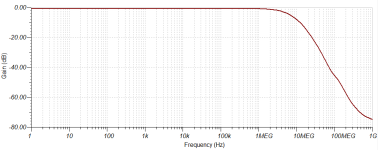
I am wondering if I can remove stability components C1 680p and R1 470R ??? Removing them in the simulation does not seem to change anything.... am I missing something?...
Removing C3 47p compensation cap actually shows a peak in high frequency, so I am sure it is good idea to keep it.
Removing T5 (feedback transistor) does not seem to change anything except higher THD. Is it safe to just leave T1 ???
Just wondering....
Removing C3 47p compensation cap actually shows a peak in high frequency, so I am sure it is good idea to keep it.
Removing T5 (feedback transistor) does not seem to change anything except higher THD. Is it safe to just leave T1 ???
Just wondering....
Attachments

H
HAYK
Can also bring it up to 22k frequency and do transient test in analysis around 10u to 50u
See any ringing.
Not sure if your gonna AC couple the input / outputs in the application.
could add input/ output cap
When testing for stability or distortion. I'll add internal resistance to the voltage sources.
For High power amps ill use 1 to 1.8 ohms. small signal circuits 3 to 10 ohms.
Then you have to add power supply decoupling caps.
and then test input source with 300 to 1k or close to what the impedance would be in real life coming
in.
with internal resistance/ input decoupling id expect it to behave like many discrete opamps.
which will still be good around .001 to .003 % distortion. Then at high frequency around 20/22k
expect .01 to .03 % distortion.

I did square wave transient at 22 kHz
no major ringing.
If I remember when playing around with the 2N7000
that is what I added R1 - C1 in your schematic post #95 because at 20 kHz
there was ringing without it.

See any ringing.
Not sure if your gonna AC couple the input / outputs in the application.
could add input/ output cap
When testing for stability or distortion. I'll add internal resistance to the voltage sources.
For High power amps ill use 1 to 1.8 ohms. small signal circuits 3 to 10 ohms.
Then you have to add power supply decoupling caps.
and then test input source with 300 to 1k or close to what the impedance would be in real life coming
in.
with internal resistance/ input decoupling id expect it to behave like many discrete opamps.
which will still be good around .001 to .003 % distortion. Then at high frequency around 20/22k
expect .01 to .03 % distortion.
I did square wave transient at 22 kHz
no major ringing.
If I remember when playing around with the 2N7000
that is what I added R1 - C1 in your schematic post #95 because at 20 kHz
there was ringing without it.
Not sure if your gonna AC couple the input / outputs in the application.
could add input/ output cap
I have 100uF / 1K HP filter in the next stage which is amplifier (made of two paralleled chipamps).
I am not sure if I should use input decoupling though....
I could add 10uF bipolar electrolytic cap and increase 47k resistor to say 100k to move cut frequency way into inaudible territory...
By the way, is there a formula to calculate RC filter at say -0.1dB. I know the -3dB one looks like this: 1 / [2*Pi*R*C]
Oh yeah that is right. Seen that amplifier thread.
Should have left a comment, that was pretty fun parallel chip amp.
Dc would be blocked by its input cap. All good.
It was more towards, I just tried my best to sim.
with less ideal voltage sources/ current sources
To look at stability and add everything that may be there in
real world.
When playing around with the 2N7000 it was stable in the model.
At unity gain. Then changing things in sim. Seen the ringing at high freq
So its just fun to try and cover stability in sim, or how to make
stability issues appear in sim. many times they seem rather stable
with simplified models
Yes I noticed you mentioned 2n7000.
I’m working on PCB layout. All smd components. Got this smd hot plate from Amazon- should be fun to “bake” that unity buffer. And then test for stability. Worst case will add cap and resistor in the next revision.
Excited to hear those few LS844 in sot-23-6 that I got for under $3 btw
I’m working on PCB layout. All smd components. Got this smd hot plate from Amazon- should be fun to “bake” that unity buffer. And then test for stability. Worst case will add cap and resistor in the next revision.
Excited to hear those few LS844 in sot-23-6 that I got for under $3 btw
- Home
- Source & Line
- Analog Line Level
- Need help simulating discrete impedance matching buffer in LTSpice - using 2N7002 and BC856