The power FET will have a much higher gate/source junction capacitance for one thing and the noise will be high compared to a JFET. I'm pretty sure the small signal gain or transconductance will be low for the FET.
I made some very rough measurements of MOSFET noise a while back and 2N7002 took the prize of being the noisiest of all. But there are various manufacturers of this device and they're unlikely to be all equal in noise. Mine were ChangJiang, a Chinese brand.

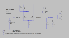
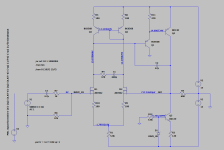
Ok, another iteration of the schematics achieves minimum THD because I run high current through MOSFETS and BJT. 14mA/2 = 7mA each MOSFET and 20mA BJT. I hope they will not get too hot. Because in that configuration I get best THD down to 0.005% at 1V input.
It is able to handle input up to 6.5Vpp.
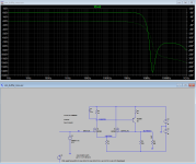
Frequency response looks ok, not the best I suppose. I am trying to minimize parts count and at the same time get stable performance.
Step response is something I cannot figure out. It rings no matter what I do.
Attaching LTSpice sim file to this post.
It is able to handle input up to 6.5Vpp.
Frequency response looks ok, not the best I suppose. I am trying to minimize parts count and at the same time get stable performance.
Step response is something I cannot figure out. It rings no matter what I do.
Attaching LTSpice sim file to this post.
Attachments
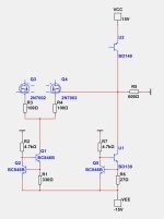
low part count challenge to drive 600 ohms with fet input.
it is interesting playing around with those 2N7002
little picky , that is the fun right
constant current sources probably help too.
but simplicity is simplicity
it is interesting playing around with those 2N7002
little picky , that is the fun right
constant current sources probably help too.
but simplicity is simplicity
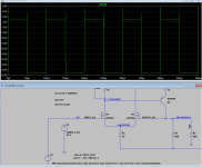
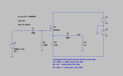
Should be able to get 10Vp - 20Vpp at .0006% with this belowI get best THD down to 0.005% at 1V input.
It is able to handle input up to 6.5Vpp.
is about .006% before clipping, driving 600 ohms
Looks nice!
Why BD140? I’m assuming it allows for higher output current, but it looks like amplifier output stage transistors lol. I guess that’s what it takes to drive 600 ohms loads. But are there any other transistors in SMD packages that can do the job? Or any other that can be used there?
So distortion reduced because of current sources?
They are constant current sources, 2mA and 25mA.What are those IS1 and IS2?
They are missing in your test.
Real life it will still want 60 to 70ma to get good swing.
Its class A output so current is massive.
Since ideal current source in model is beautiful impedance
I can weasel good swing with 25ma.
I tested with internal resistance
and simple current source. still manages .003%
could probably try feedback current source.
I just nailed it open with Zener for 58 ma
I guess the ability to drive low loads at low distortions requires a lot of parts…
It would be nice to reduce parts count, but what parts can we get rid off without significant drawbacks?
Two 2N7007 are needed as well as BD140, BD138 for the output current drive ability.
What about T4, T3 pair? T1? Should we get rid of those?
It would be nice to reduce parts count, but what parts can we get rid off without significant drawbacks?
Two 2N7007 are needed as well as BD140, BD138 for the output current drive ability.
What about T4, T3 pair? T1? Should we get rid of those?
Last edited:
Real life it will still want 60 to 70ma to get good swing.
Its class A output so current is massive.
Since ideal current source in model is beautiful impedance
I can weasel good swing with 25ma.
I tested with internal resistance
and simple current source. still manages .003%
could probably try feedback current source.
I just nailed it open with Zener for 58 ma
View attachment 1173793
If I were to build this, what is the sequence of verifying that it is working as it should. What test points should I provide on the PCB? What parts I may need to adjust (provision additional soldering pads)?
How much power is dissipated in those BD140 and BD139?
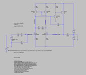
Finally it works in LTSpice 🙂
I only will need about 6Vpp swing, and so changed resistor at BD139 emmiter to 470 ohms. That reduces current to 17mA. Is that safe change to make?
Zener diode is at 8.2V? Can I substitute that to 5.1V zener?
Can I increase 47p capacitor to 100p?
I only will need about 6Vpp swing, and so changed resistor at BD139 emmiter to 470 ohms. That reduces current to 17mA. Is that safe change to make?
Zener diode is at 8.2V? Can I substitute that to 5.1V zener?
Can I increase 47p capacitor to 100p?
Attachments
Last edited:
Class A output, most power is idle
so depending on current of DC around .75 to 1.2 watts
AC current to 600 ohms around .06 watts
your on low side so just assume you need package for at least 1 watt
at elevated temperatures. not the 25c datsheet rating.
Some people derate to 70% some 50% for transistors
for quick calculations basically need 1.5 to 3 watt transistor package
- Home
- Source & Line
- Analog Line Level
- Need help simulating discrete impedance matching buffer in LTSpice - using 2N7002 and BC856