Hello again,
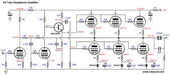
I am working on a version of the Over/Under design from TubeCAD to drive my current and future headphones. With the ECC99s as designed in the blog i got sub percet THD in LTSpice but after adapting it for the ECC88 i cant seem to get the THD bellow a few percent.
The goal is to drive headphones from 50 to 300 ohm, mainly 130ohm and up.
With the values in the LTSpice picture attached i am getting about 2.14% THD and mainly third and fifth order and id rather have the evens over the odds 🙂

The THD seems to decrease with higher loads as the amp goes more and more into class AB rather than A so i belive i should be looking at changing the bias of the tubes?
The input of 2.97V is the max output of the DAC that will be used. I am also looking to replace the MJE BJTs for some modern alternatives so suggestions on that front are welcome.
I am working on a version of the Over/Under design from TubeCAD to drive my current and future headphones. With the ECC99s as designed in the blog i got sub percet THD in LTSpice but after adapting it for the ECC88 i cant seem to get the THD bellow a few percent.
The goal is to drive headphones from 50 to 300 ohm, mainly 130ohm and up.
With the values in the LTSpice picture attached i am getting about 2.14% THD and mainly third and fifth order and id rather have the evens over the odds 🙂
The THD seems to decrease with higher loads as the amp goes more and more into class AB rather than A so i belive i should be looking at changing the bias of the tubes?
The input of 2.97V is the max output of the DAC that will be used. I am also looking to replace the MJE BJTs for some modern alternatives so suggestions on that front are welcome.
Attachments

The ECC88 isn't as beefy as the ECC99/12BH7/6CG7 etc so can't deliver as much current, though I'm not sure if that is the issue here.
The MJE340/350 are absolutely fine for this application, I've used them in several amplifiers I've built in CCS. Re your original issue, you could try different value's for R9, this dictates what current the CCS is set to and thus bias. In my amps in my CCS's I use a preset and fixed R for the emitter resistor so I can vary the bias and set for the best balance (when used for LTP phase splitters) or best THD in cathode followers, this is R9 in your schematic.
That said center bias or a tad either side of center bias usually can't be improved on to any great degree, have you drawn a loadline?

How about using the tubes in a white cathodefollower configuration, augmented by tranistors to deliver tube controlled additional current?
Because I have a stack of ECC88s laying around and I'd like to use them 🙂Why not continue to use ECC99 ( or 12BH7 ) ?
I think I want to stick to this topology, and the current draw isn't an issue. In fact if I put a bigger load on it the THD in LTSpice improves significantly, if I was happy to just use 60 ohm headphones I'd build it right now 🙂How about using the tubes in a white cathodefollower configuration, augmented by tranistors to deliver tube controlled additional current?
The MJE parts are definitely good enough for the application, the reason I wanted to change them was because they are so vastly over specced for the application and not especially cheap either. Not really that bad, just thought there would probably be more suitable options around.The ECC88 isn't as beefy as the ECC99/12BH7/6CG7 etc so can't deliver as much current, though I'm not sure if that is the issue here.
The MJE340/350 are absolutely fine for this application, I've used them in several amplifiers I've built in CCS. Re your original issue, you could try different value's for R9, this dictates what current the CCS is set to and thus bias. In my amps in my CCS's I use a preset and fixed R for the emitter resistor so I can vary the bias and set for the best balance (when used for LTP phase splitters) or best THD in cathode followers, this is R9 in your schematic.
That said center bias or a tad either side of center bias usually can't be improved on to any great degree, have you drawn a loadline?
I'll play around some with R9, I belive it should be a value close too R6 though to keep balance so maybe I'll play around with that further.
I dont understand what you mean by this? Could you explain further? Do you mean that the load on the tubes is too low or that the simulated headphones are off too low impedance?The load impedance of 50 to 300 ohm is much to low to get any decent distortion figures
@rayma what would be the benefit of using another tube section for each place? This has enough power for any headphones i have, it is just the THD that is an issue right now
Your headphones are the load. The tube has to feed current to your headphones.
The lower the impedance of the headphones, the higher the current demand and the higher the distortion.
Triodes are at there best when feeding a HIGH impedance load. When they have to feed a load lower than their own plate resistance they are only able to produce low power and high distortion. Think of it like car engine that produces a certain power at certain rpm. Your low impedance headphones are a very heavy load, just as trying to pull a very very heavy physical load in fifth gear, your engine would not be happy. Thats why tubes usually use transformers to transform a low impedance load to a more suitable high impedance load.
If you insist on using your large stash of ECC88 tubes . . .
Then try this:
Purchase a real good set of Push Pull Output transformers.
(You may have to get a custom build to get multiple output taps).
Then get a real good CCS for the cathodes that are tied together (Constant Current Sink), and build a self inverting push pull amplifier.
You should be able to get low distortion, if you are creative.
Simple, yes.
Cheap, no.
"Good is not cheap, cheap is not good" Frank Reps in Sound Practices magazine, "Baby Ongaku" 2A3 amplifier article.
Happy designing, building, and listening!
Sure, that much I understand, but this amp puts out much better THD numbers at 60 ohms of load than 130 or greater even up too 600 ohms like a pair of Sextets. I'm trying to shift that point of lowest distortion to something like 150 ohms. Seems like a bias thing, where this design strongly prefers class AB operation rather than class A?Your headphones are the load. The tube has to feed current to your headphones.
The lower the impedance of the headphones, the higher the current demand and the higher the distortion.
Triodes are at there best when feeding a HIGH impedance load. When they have to feed a load lower than their own plate resistance they are only able to produce low power and high distortion. Think of it like car engine that produces a certain power at certain rpm. Your low impedance headphones are a very heavy load, just as trying to pull a very very heavy physical load in fifth gear, your engine would not be happy. Thats why tubes usually use transformers to transform a low impedance load to a more suitable high impedance load.
I'd probably opt for a solid state drive stage over iron. Not that the issue is that this can't power headphones, it's very much so capable of driving all of my pairs like this, just stuck with the THD figure being too high for my liking at full tilt.If you insist on using your large stash of ECC88 tubes . . .
Then try this:
Purchase a real good set of Push Pull Output transformers.
(You may have to get a custom build to get multiple output taps).
Then get a real good CCS for the cathodes that are tied together (Constant Current Sink), and build a self inverting push pull amplifier.
You should be able to get low distortion, if you are creative.
Simple, yes.
Cheap, no.
"Good is not cheap, cheap is not good" Frank Reps in Sound Practices magazine, "Baby Ongaku" 2A3 amplifier article.
Happy designing, building, and listening!
While I do have quite a few ECC88s, I don't have four per channel amounts of them 😛Here's a more recent design.
https://www.tubecad.com/2021/12/blog0549.htm
That phase inverter for the lower tube using the output of the top tube is making the push-pull inherently unbalaced for distortions
And without negative feedback , low load for tubes I'm surprised that distortions are not much higher .
And without negative feedback , low load for tubes I'm surprised that distortions are not much higher .
@Depanatoru the phase inverter is designed to keep the tubes swinging the same current, I recommend reading the tubecad blog about it because it is quite fascinating 🙂
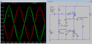
You don't tell us what spice models you are using.I am working on a version of the Over/Under design from TubeCAD to drive my current and future headphones. With the ECC99s as designed in the blog i got sub percet THD in LTSpice but after adapting it for the ECC88 i cant seem to get the THD bellow a few percent.
You may have an inadequate or broken model for ECC88;
try this (my sim and model in the zip file) ... and don't start evaluating THD at time zero ,,,
I get 0.09% with Ayumi model for ECC88 and 0.14% with Ayumi ECC99, and THD rise with increasing load ...
Attachments
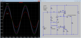
You can improve THD figure further by:
1) Ensuring that there is equal DC voltage across each top and bottom tubes
2) Use higher Hfe complimentary pairs of transistors, MJE340/350 perform better than MPSA42/92.
1) Ensuring that there is equal DC voltage across each top and bottom tubes
2) Use higher Hfe complimentary pairs of transistors, MJE340/350 perform better than MPSA42/92.
Attachments
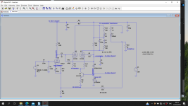
This is something I built and works very well. Its similar to Mr Summer's suggestion. The transformer is a 1VA5 mains 120-0-120V 24V toroid. It rolls off at 8KHz due to the (simulated C1) primary capacitance. However the negative feedback results in a flat response. Headphones are not designed to be driven from low output impedance unlike speakers so you may wish to add 47R in series with the output. The HT only needs to be 100V but you can scale this to anything higher.
https://uk.farnell.com/multicomp/mc...al-2-x-12v-1/dp/9531319?st=transformer toroid
https://uk.farnell.com/multicomp/mc...al-2-x-12v-1/dp/9531319?st=transformer toroid
Attachments
Last edited:
I'm using the model from the big pack early on in in the spice models thread here on the forum, maybe not the best as those are fairly old? Will try it with your model 🙂You don't tell us what spice models you are using.
You may have an inadequate or broken model for ECC88;
try this (my sim and model in the zip file) ... and don't start evaluating THD at time zero ,,,
I get 0.09% with Ayumi model for ECC88 and 0.14% with Ayumi ECC99, and THD rise with increasing load ...
As for the THD at zero, I belive the default four command does THD for the last period? Was a while since I read the documentation on that though.
Thank you, will check further 🙂You can improve THD figure further by:
1) Ensuring that there is equal DC voltage across each top and bottom tubes
2) Use higher Hfe complimentary pairs of transistors, MJE340/350 perform better than MPSA42/92.
I don't know what's going on, but can say fersure, fersure that it's not possible for triodes to have decreasing distortion with steeper loading, or to have decreasing distortion with class AB operation rather than class A, without being in overload. The curves just don't work that way. Could you be seeing some clipping effect? Or is this a modeling error?
All good fortune,
Chris
All good fortune,
Chris
- Home
- Amplifiers
- Tubes / Valves
- Need help reducing THD in ECC88 Over/Under design