He's probably witnessing distortion cancellation. It can be very prevalent in heavily loaded tube stages.I don't know what's going on, but can say fersure, fersure that it's not possible for triodes to have decreasing distortion with steeper loading
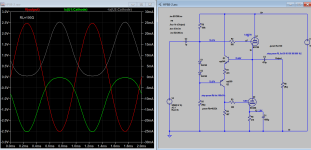
100 ohms is about lowest load you can use with a pairs ecc88, heavier load will exhaust the current limit of the output tube and became rounded, therefore higher distortion. This is Class AB amp with cross overlap of about +-7mA, which is determined by amount of grid bias. With 1 just pairs output the gain would be < 1 (unity). Distortion depends on the load value, what you see is distortion under different loads, not just one fixed load. The lighter the load, the higher the output (more gain) and less distortion. The distortion figure is very reasonable as long as plate current is not exceeded or saturated.
Attachments
Last edited:
Because I have a stack of ECC88s laying around and I'd like to use them 🙂
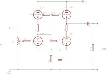
Try the use of Gomes circuit without any sand in the middle.
Just to try.
Attachments
I think you're in the wrong threadIf you would like low distortion my advice is to build a wolverine amplifier. Tested actual distortion at 1Khz is 0.000009% 80wrms 8 ohm load.

Well, replaced the model and the THD went down to 1.3% with the 130 ohm load, but loaded with 60 ohms it is still significantly better. Perhaps as @Merlinb says i am seeing cancellation because it seems to be a very narrow area around 60 ohms that has this sub percent distortion.
Removing C3 and C4 makes the THD around 7% so that dosent seem right.
Trying to even out the voltage across the tubes more made it worse, back to ~2% THD for 130 ohms but better for 300 ohm and up, but still best at 60 ohms.
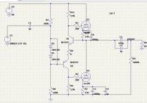
I have attached my LTSpice file and the models i used for the MJE parts if anyone wants to see for themselves. Maybe somethings just up with my LTSpice install? 😀
Removing C3 and C4 makes the THD around 7% so that dosent seem right.
Trying to even out the voltage across the tubes more made it worse, back to ~2% THD for 130 ohms but better for 300 ohm and up, but still best at 60 ohms.
I have attached my LTSpice file and the models i used for the MJE parts if anyone wants to see for themselves. Maybe somethings just up with my LTSpice install? 😀
Attachments
Well i was able to get well into the sub percent region of THD by just running a shorter simulation. Doing a 5ms simulation instead of a 2s one brought down the THD from 1.27% to 0.046%. Not really sure why this changed anything but it sure did
This gives me THD numbers im happy enough to procede to building with, but i kind of want to know why this helped so much so i know if they are "real" numbers or not
This gives me THD numbers im happy enough to procede to building with, but i kind of want to know why this helped so much so i know if they are "real" numbers or not
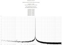
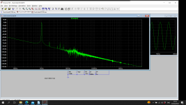
Set the minuimum step size to 1us and check you are simulating over a whole number of cycles. Post an FFT of the output waveform.
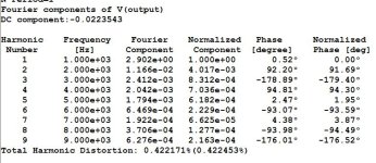
Setting the min step size to 1u increased the THD by about 0.02%(From 0.03 to 0.048%), here is the FFT:

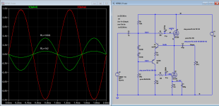
Just simulating your design. You are just on the edge of class B operation if you look at the currents in the ECC88's. There is a slight shift in the DC operation conditions when you run the 2s simulation which will add to the distortion.
Changing the component values slightly changes the 2'ns harmonic by large amounts. You have tuned the resistor values (R7, R9) to get a null. That's a rabbit hole. However tolerances in the valves themselves will mean that this won't be achieved in practice. So care is needed in simulation here to try a spread of values. With a LTP LT spice will simulate a perfect balance as the transistors are the same. I've sometimes used mismatched valves to see what happens. Try and find something similar to a ecc88 or use two different models.
Well so because of this DC shift, i have changed to running a 10 second simulation to be more sure that everything has settled in and im only saving the last second. These simulations guided me to a lower bias resistor R7 down to 270 ohms to get 0.86% from 130 to 600 ohms.
The new fun phenomena is that 60 - 80 ohms is at 0.6% THD and then 80-100 ohms is at 0.9% 😅
I think this seems pretty alright at least, its nothing fantastic but it seems to beat the simulation of my current hybrid amp in both output power and THD(Current amp can only swing 500mV and has a simulated THD of 2% 🙂 )
If you add front end gain you can mop up some more of the distortion with some negative feedback.
For lowest distortion use .plotwinsize=0
Im my example, parameterized frequency f is used in sine source, fourier statement, and simulation Stoptime and Maximum Timestep.
Simulation of a few cycles is now enough to get low distortion figures. See attachment (use include files from previous posts)
Im my example, parameterized frequency f is used in sine source, fourier statement, and simulation Stoptime and Maximum Timestep.
Simulation of a few cycles is now enough to get low distortion figures. See attachment (use include files from previous posts)
Attachments

H
HAYK
If there is a low DC creep that only settles after a few seconds, how does this help? This just seems like taking the first cycle which seemed to produce unrealistic results?For lowest distortion use .plotwinsize=0
Im my example, parameterized frequency f is used in sine source, fourier statement, and simulation Stoptime and Maximum Timestep.
Simulation of a few cycles is now enough to get low distortion figures. See attachment (use include files from previous posts)
- Home
- Amplifiers
- Tubes / Valves
- Need help reducing THD in ECC88 Over/Under design