I am pretty sure that LTspice can't give too low distortion figures. I know that you get too high values if the settings are sub optimal. (Maximum Timestep not properly defined, and missing .plotwinsize=0 statement)
Sandro has some great videos on optimizing LTspice for the least amount of distortion. A bit overkill for tube amps I think, but very thorough.
video 5.5.1
video 5.5.2
https://www.diyaudio.com/community/threads/sw-vfa-01-audio-power-amplifier-video-series.347673
Sandro has some great videos on optimizing LTspice for the least amount of distortion. A bit overkill for tube amps I think, but very thorough.
video 5.5.1
https://www.diyaudio.com/community/threads/sw-vfa-01-audio-power-amplifier-video-series.347673

Defined the max time step as 0.5u and added the .plotwinsize = 0 and the numbers improved drastically 😀 Down to 0.0566% from ~0.86% with a 130 ohm load!
Even more confident in this design now and will go ahead with the project 🙂
Even more confident in this design now and will go ahead with the project 🙂
PCB prototypes have been orderd, i expect them to arrive sometime next week. Will have to work on getting a decent 150V PSU up and running whilst those are getting made. Hopefully i have not made any grave errors in my routing and design 🙂
What I can’t understand is the attitude to play with simulation also around not complicated circuitHopefully i have not made any grave errors in my routing and design 🙂
With a in air cabling one socket and a simply power supply you can these live the circuit and in case modify to reach the best performance
With the use of a good sound card and Arta o REW software is possible to have a real test
Had to make a PCB for a cource i am taking and the electronics lab i have available is filled with people i dont want anywhere close to a sensitive somewhat high voltage circuit. The PCB has two parts, a DAC i have been wanting to prototype for about eight months and this amplifier was able to be snuck onto the same board. Just made sense in this situation to me as the extra cost was almost nothing and i cant work freely in the lab at the moment. 🙂What I can’t understand is the attitude to play with simulation also around not complicated circuit
With a in air cabling one socket and a simply power supply you can these live the circuit and in case modify to reach the best performance
With the use of a good sound card and Arta o REW software is possible to have a real test
I've been following this interesting thread and would like to ask if there's a working outcome ?
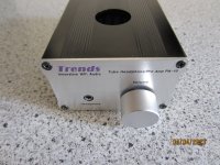
Here's quite af different way to drive a headphone incorporating an ECC88/E88CC into the circuit.
This works quite well, I would say much better than expected.
Running on 24VDC supply voltage you don't have to worry about any HT.
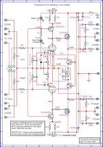
Having to do repairs to one I took the opportunity to reverse-engineer it and draw the schematics.
Just fyi, not trying to convince anyone of anything.
Rgds,
/Torben
Here's quite af different way to drive a headphone incorporating an ECC88/E88CC into the circuit.
This works quite well, I would say much better than expected.
Running on 24VDC supply voltage you don't have to worry about any HT.
Having to do repairs to one I took the opportunity to reverse-engineer it and draw the schematics.
Just fyi, not trying to convince anyone of anything.
Rgds,
/Torben
Attachments
Hi, I have spent most of my time trying to get the DAC to output anything with no success.
Right now I'm stuck with the PSU going flat as soon as I plug in both the filament and HT. Absolutely lost on why as there are no shorts or severe current limits and so on.
Haven't looked at it for a month though because I've been occupied with other stuff.
That circuit looks interesting, I have all of that besides the KSP part but I belive that just sets bias so it could be swapped quite easy. Might whip that up honestly
Sorry to hear about your problems with the PSU. Remember that the filament resistance could be close to zero ohms in cold state. Would that trip any current limits in the PSU ?
The KSP circuit is not setting the Bias, it's a CCS (Constant Current Source). Bias is set with the 2K pots in the cathodes. Bias should be set to measure 16,5V on anodes iaw the users guide. THD seems to drop somewhat when adjusting for 15,5V on anodes instead.
The CCS is necessary instead of a regular anode resistor as the supply is only 24V. No room for a large voltage drop here but you still need a large impedance to work into. The CCS solves that problem. Replace the KSP with a transistor with a large gain as it will give you the highest CCS Z-out.
What kind of vacuum tubes are in this amplifier in Post # 48 that works with only 24 Volts B+ ?
Is that design supposed to be a Hi Fi Stereo Headphone amplifier?
Does it sound like a guitar fuzz box?
Is that design supposed to be a Hi Fi Stereo Headphone amplifier?
Does it sound like a guitar fuzz box?
It is sounding nothing like a fuzz box.
I'm using it with a vintage Sennheiser HD-414 headphone and it's sounding (and measuring) very fine.
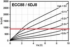
ECC88 wasn't made primarily for low B+ operation but that doesn't mean it won't function. Take a look at the Ia/Va plot attached, originally made by Merlin Blencowe. It doesn't show Va all the way to 16.5V but you'll get the idea. The red loadline shown is for the amp. in #48 and it is of course horizontal because of the CCS.
I'm using it with a vintage Sennheiser HD-414 headphone and it's sounding (and measuring) very fine.
ECC88 wasn't made primarily for low B+ operation but that doesn't mean it won't function. Take a look at the Ia/Va plot attached, originally made by Merlin Blencowe. It doesn't show Va all the way to 16.5V but you'll get the idea. The red loadline shown is for the amp. in #48 and it is of course horizontal because of the CCS.
Attachments
Last edited:
Measurements of various ECC88 tubes at very low plate voltages has been carefully done.
One of the things the low plate voltage measurements showed was that some ECC88 tubes had far more grid current than other ECC88 tubes.
All ECC88 tubes are Equal, just some ECC88 tubes are More Equal than others.
Hand selection of tubes works!
One of the things the low plate voltage measurements showed was that some ECC88 tubes had far more grid current than other ECC88 tubes.
All ECC88 tubes are Equal, just some ECC88 tubes are More Equal than others.
Hand selection of tubes works!
I only tried out various NOS ECC88 and E88CC tubes in this amp. and all worked well.
That is AFTER the anode-voltage was set on 16.5V as recommended by the manufacturer or at 15.5V as recommended by my oscilloscope doing a FFT. Harmonics at Va = 15.5V were considerably reduced at testfreq. 1KHz.
From the handfull of tubes tested none had any problems being set to the correct anode voltage or showed worse harmonic distortion than others.
Perhaps I just got lucky ?
The amp. ended up with a NOS Siemens E88CC. Not because I noticed a remarkable improvement in performance compaired with other but because I expect it to outlive any others I have on hand.
The users manual for the amp. is attached.
Rgds,
/Torben
Attachments
The output stage is transistor/mosfet and voltage amp is ecc88. But that's what the manual says - no false claims its a valve headphone amp.
The output is Mosfet.
The transistor is another CCS (Constant Current Sink), this time as a load for the Mosfet and at the same time supplying 150mA per channel, in all 300mA current for the tube filament.
Voltage amplification is done by the ECC88/E88CC exclusively as the Mosfet is a simple Source-follower / Impedance-converter with a gain of a bit less than 1.
I'm concerned this thread is focusing on the Trend-amp instead of Bananasplit_00's ECC88 project.
I'm not trying to hijack the thread but at the same time I'll be happy to answer any questions if it's OK with Bananasplit_00.
Rgds,
/Torben
It's a very interesting project, but I think it could do with it's own thread 🙂 might build a copy if I find my MJE150030s, I have a somewhat similar amp with tube voltage amplification(ECC82) and MOSFET output and find it quite nice. That runs on 12V. Might be fun to compare, but for now I want to get this project working.
I have absolutely no clue what's up with the PSU, seems like the issue is only there when both filament and HT are connected maybe? I have tested both and they seem to deliver what is expected on their own...
I have absolutely no clue what's up with the PSU, seems like the issue is only there when both filament and HT are connected maybe? I have tested both and they seem to deliver what is expected on their own...
I finally figured out the PSU issue!
The PCB fab had run out of the 100k resistors i was going to use, the website suggested i replace them with an in stock part, i accepted and it turns out they replaced them with not 100k resistors, not 10k, 1M, 100 ohm even... the suggested part was ONE ohm............
PSU now no longer goes to 2V on the HT rail! glad i have a 100mA limit on that so nothing caught fire 😀
Expect some progress soon!
First glow and first 1kHz tone complete 😀
A few things to look at next. Need to increase the filament voltage and I only had sound on one chanel. The latter is probably just a bad solder joint from replacing the resistors and the former should be a twist of an adjustor away. Just ran out of time for today.
Need to clean up the output of the PSU a bit too, there was noticeable 50Hz left so I'll have to do some more filtering for sure
Nothing new to show but as expected it was just a bad solder joint that was holding back one chanel 😀
Redid the PSU, now running AC heaters and I have a CLC filter on the output. The caps are 820uF and the inductor is marked 5000MH which could be either 5000uH or 5000mH. Either way it works beautifully!
I am amazed at how black the background seems to be, can't perceive any noises when now playing anything and this is in a room full of EMI awfulness in the audible range!
Now to the next three issues: the heaters are a bit too hot, bass is very thin and I need a voltage amp if I am going to keep using my phone for testing. As this is a current amplifier, the gain is actually less than one 😅
- Home
- Amplifiers
- Tubes / Valves
- Need help reducing THD in ECC88 Over/Under design