Hi all,
I've had another thread started on help with the box and adding a helper woofer (here) , but I really need some help with integrating BSC.
The speakers: 12" Tannoy CMS 1201 DCT ceiling speakers with no BSC
A basic 2 way with 2nd order low- and high-pass
Stock XO:
1.75 mh series > 25 uf parallel > woofer
6.8 uf series > 0.22 mh & 8.2 ohm parallel > tweeter
First off, I do not have software or measurement equipment. I did look up how to simply add BSC via additional RL circuit, I did add it and it worked. I used components on hand that were close to what the online calculator suggested: 2.3 mh with 5.2 ohm parallel resistor for 6db of BSC, added that in front of the existing passive, then padded the tweeter a little until it sounded balanced.
I'm looking for a more elegant / simpler solution that limits the number of added components in the passive, and hopefully doesn't affect phase like doing what I did.
EDIT: 6db isn't cutting it, I think they really need 8db of BSC.
The cabs are 14.25" wide
Woofer RE is 5.1 ohm
Tweeter RE is 3.9 ohm
Thank you very much to anyone who can chime in and help me pick components to order. I'm going 15ga on the inductor so it's pricey, plus going with Mills resistors. In other words, I'd hate to order more than I need 🙂
Last edited:
Forgot to mention, my goal is 6db of BSC, the speakers need every bit of that.
The woofers are bass shy due to high FS around 60 - 70 hz and real high QTS around 0.6
Right now the drivers are just mounted in the test enclosure of 48 liters and ported to 53 hz via 3 x 2" ports. The final cabs will be a touch smaller only and have the stated 14.25" width baffle, I will slot port that to a similar 50 - 55 hz.
If you run your 15" up to the baffle step frequency, you will have the compensation done without adding anything to the original woofer crossover. Naturally this also means a smaller inductor for the 15".a more elegant / simpler solution that limits the number of added components in the passive
Your tweeter response should not need to change (only come down 6dB). You should pad it carefully to keep the impedance looking similar to before.hopefully doesn't affect phase like doing what I did
If you run your 15" up to the baffle step frequency, you will have the compensation done without adding anything to the original woofer crossover. Naturally this also means a smaller inductor for the 15".
Your tweeter response should not need to change (only come down 6dB). You should pad it carefully to keep the impedance looking similar to before.
Thanks for your input Allen, I've learned a ton from your sticky about designing crossovers without measurement equipment, I'm sure many others have too.
I was trying to get these dual concentrics to sound as balanced as possible on their own, so they can run stand-alone. I will need to purchase dual plate amps to run the 15" woofers active, so that will have to wait a little for now.
Ok. First things I'd like to know (there are a few) is why the woofer has a filter at 700Hz, when the tweeter cuts at 4kHz. Is this already dealing with the baffle? Are both units 8 ohms? Is your baffle 15" wide? Can you show a link to the calculator, and how did you pad the tweeter?
Ok. First things I'd like to know (there are a few) is why the woofer has a filter at 700Hz, when the tweeter cuts at 4kHz. Is this already dealing with the baffle? Are both units 8 ohms? Is your baffle 15" wide? Can you show a link to the calculator, and how did you pad the tweeter?
Not sure what you mean with a filter at 700 hz?
The woofer's RE is 5.1 ohms,
Tweeter RE is 3.9
That's me measuring with a multimeter. Does that make the drivers 8 ohm nominal? Or 6 ohm?
Baffle is 14.25"
Link to calculator I used for 6db of BSC using 3.2 mh + 5.2 ohm:
HiFi Loudspeaker Design
I then padded the tweeter using a 4 ohm resistor to pad it 6db, based on your write-up. I also tried a 3.3 ohm resistor, but it wasn't quite enough padding. 4 ohm sounds about right.
Ok. First things I'd like to know (there are a few) is why the woofer has a filter at 700Hz, when the tweeter cuts at 4kHz. Is this already dealing with the baffle?
Oh I think you mean the stock XO. On paper there's a really big gap between the drivers, right? Yet the drivers are really well integrated, if anything the mids even have a slight bump rather than a scoop. It's borderline studio monitor flat, with a serious lack in bass without BSC.


Now I am beginning to understand. posting the charts and looking at the drivers was helpful. It also seems that the crossover is tailored on a finer level, it would be a shame to mess it up too far.
You could make the tweeter filter work more like the original by making it think the circuit around it is the same, while you are bringing its level down.
To do this, take out the 4 ohm resistor and put it in parallel with a 3.3 ohm. Now put these in between the capacitor and the tweeter terminal. Then put another 3.3 ohm resistor in parallel with the 8.2 ohm, and tweak it again.
The baffle step is going to happen either side of about 300Hz. Your impedance plot shows you that you have around 7 ohms there, and it is varying. I'm having a little trouble deciding between two ways of managing the woofer crossover, I might run some sims and post the results.
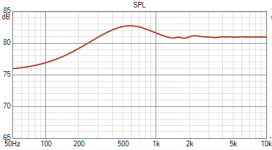
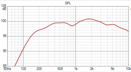
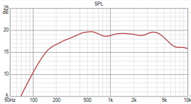
I simmed the baffle, but consider this work as an approximation.
I then added the response deviations to your posted 0 degree and 20 degree plots.
Speaking of this, you mentioned the broad upper midrange lift. This goes with a slight narrowing of the response so it may sound fine, or maybe even more so if the speakers are toed in a little?
After trying the original filter using the supplied impedance, I chose the region below 500Hz as wanting correction, so I plotted how un-flat that was up to 6dB, and made up a target response (shown yellow in the plot in the next post).
Attachments
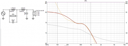
I then compared the original filter for a refit to the new response. I used a flat response driver to make it easier to visualise, using the real response is unnecessary for this if the target is right. I also used a flat impedance, the supplied one is corrupted for this purpose.
The correction as shown, would render the speaker almost flat down to 100Hz.
The correction as shown, would render the speaker almost flat down to 100Hz.
Attachments
Last edited:
I then compared the original filter for a refit to the new response. I used a flat response driver to make it easier to visualise, using the real response is unnecessary for this if the target is right. I also used a flat impedance, the supplied one is corrupted for this purpose.
The correction as shown, would render the speaker almost flat down to 100Hz.
Thank you so much for your help!
Looks like the cascading response I was looking for. That even lets me reuse the original 1.75 mh inductor, so I just need to get the 4.5s.
I've found that the speakers sound best slightly off axis, so toed in a little. The midrange bloom isn't bad at that point. I think more than anything it's the lack of bass.
It sounds like I better not mess with the high pass then, besides trying out the newly suggested way of padding the tweeter.
Thank you very much!!
Also, the Tannoy graphs I pulled from the brochure are measured on a IEC baffle, which should be similar to a ceiling (infinite baffle).
I'm mounting the drivers in a slot ported cab, so that should help the response below 100 hz down to the low 50s I'm hoping.
I'm mounting the drivers in a slot ported cab, so that should help the response below 100 hz down to the low 50s I'm hoping.
This is a situation where measurements really really help.
If you put the speakers up against a wall, your problem is solved. 🙂
If you put the speakers up against a wall, your problem is solved. 🙂
This is a situation where measurements really really help.
If you put the speakers up against a wall, your problem is solved. 🙂
Boundary reinforcement doesn't solve it with these, I put them in corners and it's still super bass shy.
First off, I do not have software or measurement equipment.
Grab a copy of Room Equalizer Wizard It's free and even with a voice grade microphone gives you much more information than listening will ever give you.
I'm looking for a more elegant / simpler solution that limits the number of added components in the passive, and hopefully doesn't affect phase like doing what I did.
Can you post a drawing of the original crossover?
Many times they try too hard and get into wildly inefficient crossover designs thinking they are working miracles.
In most cases a basic 2nd order crossover with an lpad to attenuate the tweeter usually proves more than adequate.
Last edited:
Grab a copy of Room Equalizer Wizard It's free and even with a voice grade microphone gives you much more information than listening will ever give you.
Can you post a drawing of the original crossover?
Many times they try too hard and get into wildly inefficient crossover designs thinking they are working miracles.
In most cases a basic 2nd order crossover with an lpad to attenuate the tweeter usually proves more than adequate.
Thank you about the REW tip.
I drew up the stock XO:

Also one question I had regarding the high-pass:
Does that 8.2 ohm resistor behind the 0.22 mh inductor serve as impedance correction already, or does it only affect how much is passing through the inductor?
Does that 8.2 ohm resistor behind the 0.22 mh inductor serve as impedance correction already, or does it only affect how much is passing through the inductor?
It would also be good to recheck the finer details of this crossover. For one, the resistance of the inductors needs to be investigated as these have a significant enough effect on the bass end and could take away some of the benefit.I put them in corners and it's still super bass shy.
A second issue is your wanted lower cross. This could change the performance of these and the components needed and the overall sensitivity. Thirdly, better to get the raw woofer impedance and redo things.
For now, It would be good to confirm whether you are talking more about the upper bass level giving a flat enough response for voice reproduction, or if it is the lower frequencies. It would be good to just confirm whether the region this fixes helps or not. If you have some components lying around that are similar, maybe they can be used in a custom crossover revision. Let us know if you have interesting parts.
The second one. This reduces the effect of the filter so it holds out lower.Does that 8.2 ohm resistor behind the 0.22 mh inductor serve as impedance correction already, or does it only affect how much is passing through the inductor?
I misunderstood the tweeter crossover when I first read the description. The L-pad can still be inserted between the tweeter and the filter, only the values would change. Possibly 6 ohms in parallel with the tweeter and 3 in series.
- Home
- Loudspeakers
- Multi-Way
- Need help: Adding BSC to passive 2 way Tannoy 12"