I used lousymusician's files to cross-check. Different results again, but there's always something to be gleaned. Thanks lousymusician, are these your own?
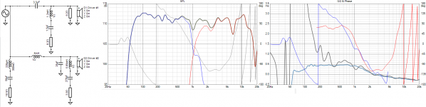
Comparing the stock crossover, to adding the 2.3mH, 5.2ohms, and 7ohms shows that the bass still doesn't reach well below 100Hz. I also think it shows you have good hearing regarding the tweeter. And maybe the 4k and up region shouldn't be falling away from 2k. Personally I go a little more as Douglas has, but the directivity of the waveguide plays a part and you are the judge.
Yes, these are measured in my 11 x 14 ft den, with REQ and the MiniDSP UMIK, and the S&L Woofer Tester II. The Tannoy is in a box measuring 24 x 15 x 12 (internal). I posted the measured TS parameters in one of KnR's other threads.
Bill
If these are two way speakers, you may be able to measure and simulate this well enough with XSim.
That is, measure the woofer in place, in the correct room location. Design your low pass filter accordingly.
That is, measure the woofer in place, in the correct room location. Design your low pass filter accordingly.
I used lousymusician's files to cross-check. Different results again, but there's always something to be gleaned. Thanks lousymusician, are these your own?
Comparing the stock crossover, to adding the 2.3mH, 5.2ohms, and 7ohms shows that the bass still doesn't reach well below 100Hz. I also think it shows you have good hearing regarding the tweeter. And maybe the 4k and up region shouldn't be falling away from 2k. Personally I go a little more as Douglas has, but the directivity of the waveguide plays a part and you are the judge.
That looks really good, thank you for modeling that.
Looking at the sim of what I have now, it seems like if I had twin subs playing to about 100hz it would be great.
Looking at your third sim, with 8db of BSC, that looks about as good as I can ever hope to get these playing stand-alone. A -3db point of 60hz and reasonably flat throughout the whole range. Put my super tweeters on top and it's a wrap.
Since the cost of the required XO components is far lower than building twin subs, or big towers with active 15" helper woofers, I will go ahead and build the suggested XO.
Looking at inductors, is it OK to go with 18ga for the woofer and tweeter? Stepping up to a larger gauge does significantly increase the cost.
Thank you!!
Slightly off topic... but....
Not to compete with anyone... but I think I should point something out about the way I do crossovers.
When I work on crossover circuitry I generally avoid series resistors and parts that couple to ground. This is in the name of efficiency. Every part you run across a speaker or to ground and every resistor you put in series, reduces the crossover's efficiency... it takes amplifier energy away from the speakers.
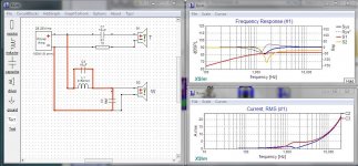
In some cases this can be really nasty. The thumbnail below shows an "amp killer" that caused so much heat as to push it into thermal shutdown at relatively low power. I've marked the current path in red and activated the current monitor panel in XSim so you can see what is going on.
As the frequency increases the current through C3 and C2 will increase very rapidly beyond the crossover point. The current chart shows it can reach 20 amps... yes 20 amps. Not many amplifiers can provide that and especially not at high frequencies.
I've seen this mistaken design advocated as an easy "baffle step" on other DIY forums and it's obviously a terrible mistake. Even when accidental paths like this aren't fatal they do detract from the efficiency of the crossover. The telling line is "These speakers sound good, but they don't really come to life until I have 100 watts on them"... So, lesson learned, I try as often as possible to create crossovers with a bare minimum of parts connected to ground.
Now for clarity, I'm not criticizing anyone. The designs I've seen here seem just fine... What I'm explaining is why my designs may seem a bit odd at times.
Not to compete with anyone... but I think I should point something out about the way I do crossovers.
When I work on crossover circuitry I generally avoid series resistors and parts that couple to ground. This is in the name of efficiency. Every part you run across a speaker or to ground and every resistor you put in series, reduces the crossover's efficiency... it takes amplifier energy away from the speakers.
In some cases this can be really nasty. The thumbnail below shows an "amp killer" that caused so much heat as to push it into thermal shutdown at relatively low power. I've marked the current path in red and activated the current monitor panel in XSim so you can see what is going on.
As the frequency increases the current through C3 and C2 will increase very rapidly beyond the crossover point. The current chart shows it can reach 20 amps... yes 20 amps. Not many amplifiers can provide that and especially not at high frequencies.
I've seen this mistaken design advocated as an easy "baffle step" on other DIY forums and it's obviously a terrible mistake. Even when accidental paths like this aren't fatal they do detract from the efficiency of the crossover. The telling line is "These speakers sound good, but they don't really come to life until I have 100 watts on them"... So, lesson learned, I try as often as possible to create crossovers with a bare minimum of parts connected to ground.
Now for clarity, I'm not criticizing anyone. The designs I've seen here seem just fine... What I'm explaining is why my designs may seem a bit odd at times.
Attachments
The next step with this is to try to make it fit with what you have and optimise a few things.is it OK to go with 18ga for the woofer and tweeter? Stepping up to a larger gauge does significantly increase the cost.
There are three inductors there, two are in series with resistors. The resistance of the inductors can be traded against the resistor value (note I've already included some nominal amount). This is the opportunity to use your inexpensive coils.
Dumb question but I assume you zeroed your meter.reads 0.5 ohm resistance
Do you do any measurements on your computer, I mean like Holmimpulse or REW, RTA/spectrum? I only ask for finding the value of the unknown inductors.I don't have a woofer tester to do anything passed basic multimeter
Dumb question but I assume you zeroed your meter.
Do you do any measurements on your computer, I mean like Holmimpulse or REW, RTA/spectrum? I only ask for finding the value of the unknown inductors.
My friend has a LCR meter, that's how I found out all the values of the inductors I've got. I will need to borrow it again to measure the unknown inductors.
With the pair of 5-ish mh inductors I've got on hand, I'll be able to mock up one speaker's crossover to see how it sounds.
Meters are notoriously bad at measuring low resistances. With a digital one, if you short the leads and there is some resistance showing, subtract that each time.zeroed your meter
They're only a few percent either way. Still, if you can wait and re-check them with the meter you could pull a few turns off one of them. Be sure to secure it (eg with cable ties) and re-check.5-ish mh
Ok, the 5.85mH shown is the 2.3, the 1.75 and the 1.8 in series. If you measure the resistance of them in series, take it off the 3.3 ohm resistor I have in the sim making sure to consider the 1 ohm listed by the inductor (in other words 4.3 ohms is wanted in total but you don't need to be too precise). The 1.2mH is the two 600uH.
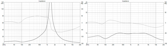
Group delay in black with excess in aqua (I delayed both drivers equally extra amounts to make the job easier but forgot to change back for this).
Some other values should be easier to find.
Group delay in black with excess in aqua (I delayed both drivers equally extra amounts to make the job easier but forgot to change back for this).
Some other values should be easier to find.
Attachments
Last edited:
Ok, the 5.85mH shown is the 2.3, the 1.75 and the 1.8 in series. If you measure the resistance of them in series, take it off the 3.3 ohm resistor I have in the sim making sure to consider the 1 ohm listed by the inductor (in other words 4.3 ohms is wanted in total but you don't need to be too precise). The 1.2mH is the two 600uH.
Group delay in black with excess in aqua (I delayed both drivers equally extra amounts to make the job easier but forgot to change back for this).
Some other values should be easier to find.
Awesome, thank you very much for doing that. I will try to assemble these XOs with the parts on hand and report back.
Thanks for chiming in. I look forward to hearing about your new subs playing with these Tannoys.
That sim you posted won't open on my macbook, any chance you could screen shot it and post it? Thanks!!
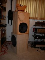
Update: The new woofers are up and running, so here's a picture. Cosmetics are not a priority at this point. The Tannoys are in boxes re-used from old projects, with the port holes blinded over. They are driven by two channels of the Modulus 86 amp at the bottom of the equipment rack. A miniDSP 4x10 HD handles EQ (4 peak cuts to flatten the Tannoy's FR but no explicit baffle step compensation) and crossover (150 Hz, LR4).
The woofer boxes are new, made from cheap 3/4 ply from the local home store. You can only see one woofer in the pic but there is a second one on the opposing side, with the magnets braced to each other and to a central brace in the cabinet. The drivers were $23/each Parts Express buyouts from several years ago, Jamo part number 30688. The 3 ft^3 box is too small for two 15's so the Q is high. The original intent was to use a Linkwitz transform to reduce the Q, but that has not yet been implemented and for now it does not seem to be a problem. The bass on this track has pretty good impact.
In room the woofers measure flat to 40 Hz, -6 dB @ 31, -10 dB @ 28. I use a couple of sharp peaks cuts in the miniDSP that correspond to room modes. The room is only 11 x 14 and I only have one real listening position so I am OK with using some EQ to flatten the bass at the listening position.
The woofers are being driven by two Breeze TPA 3116 stereo class D amps, one amp per side, one channel per woofer. That's the tiny box on the floor next to the rack, a big 30-some watts per speaker. That's not much in subwoofer land but with four 15's in a small room each of which is good for 93 dB/2.8V, I don't seem to be hurting for volume. The efficiency of the woofers just about matches the Tannoys.
This was a cheap experiment since I owned the woofers, the amps, the miniDSP, and plenty of wire. The only cost was a sheet of plywood (one sheet made two 3 ft^3 boxes including braces, I don't think I could get more volume than that) a couple of 4-post terminal cups and some more banana plugs. I think I got my $50 worth.
Next step, biamp the Tannoys using the remaining two channels of Mod 86. Maybe in January.
Bill
Attachments
- Home
- Loudspeakers
- Multi-Way
- Need help: Adding BSC to passive 2 way Tannoy 12"