those are junction FETs so it won't really matter, anyways ... drain and source are interchangeable. but don't screw up the gate!😉Guys can someone confirm the way I marked the 2SJ103 JFet pins are correct? DGS--- Please....
I think I will draw a layout for this (power SIC Fet) version.
Thank you

Today I finished another amplifier JUMA's Cubie 3.
It is a Hitachi lateral mosfet amp.
Biased into a couple Watt in to Class A.
Rail voltage 37 to 38V and bias set up 520-530 mA. Comfortably warm.
It is a keeper amplifier, sounds good but at the moment I prefer the Kaneda over the Cubie.
It has more air, more separation, not that (too) soft, smooth lateral sound. A bit more punch, somehow a bit faster or more dynamics.
I know the Kaneda can be improved even more with a bit higher bias and some better capacitors on the PCB.
I am happy to the Cubie also, now I have 2-3 amp as tool I can compare those when I try to improve sound wise.
While I work on one amp I can listen the others.
The Cubie was built all exotic parts, not much to do there, just need some time to break in!
Greetings
Attachments
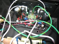


Today something total different on the test bench. A Musical Fidelity A 1 clone.
Only one channel up and running (finished).
Both channel OK but I run out basic stuff like signal wire, solder etc. I may use what I find for testing.
That one channel up and running on 25V rail voltage 1A bias.
Would love to compare to the original M Fidelity which came back to the market, was revived.
To early to say anything about the sound other than it is very promising.
My test heatsink is to small, I can not run it more than one hour at the time.
- That is not the final amplifier build, it just the testing wood model.
I am happy because both channel alive (under power), biased, working. No smoke no burning etc.
Last 10-15 years I populated several amplifier kits / PCBs and never tested, now I have sometimes and I have appetite to test them.
Some pictures
Soon I test Fab's USSA 3 also.
Attachments


Absolutely cool,
as you /we might have guessed, I think the project and the three representatives are great.
🙂
Have fun comparing them,
I'm already looking forward to your upcoming descriptions of the results.
greetings,
HBt.
as you /we might have guessed, I think the project and the three representatives are great.
🙂
Have fun comparing them,
I'm already looking forward to your upcoming descriptions of the results.
greetings,
HBt.
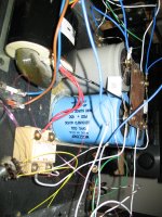
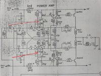
I have a question
On the schematic there are 4 piece of 1N4148 diodes (I marked with red). How important those, please see the picture?
Does those diodes influence the performance (sound) of the amplifier or only for safety purpose?
All the schematic I find on the net it include those diodes!
The PCB I purchased does not have neither the parts list include those. I wanted to ad those but I forget.......
The amplifier up and running, both channel.
Some instrument sounds wonderful like piano, strings, sax etc, vocals are also nice.
But when it come to the whole music I wish it could have more separation between the instruments.
The bass a bit clouded, like greasy bass strings, Not to bad but it is there.
Maybe the DC blocking Wima capacitors? I sow people upgraded the orig M Fidelity and they used Wima also instead the 1uF electrolytics.
Of course it needs more time to break in, also those large can caps (they are not bypassed with smaller caps) with some amp tend to produce that type of sound! Soon I will replace the capacitors bank with the one I plane to use in the final build.
This amp runs hot, very hot!
Of course I will use bigger heatsink. At the moment all 3 of my other amplifier outperform this.
Not bad sounding amplifier but that is the truth.
The N Pass F5 with Toshiba power mosfets, the JUMA amplifier and the Kaneda to. My favorite still is the Kaneda before the Juma's amp.
Again it is too soon for the final evaluation and I plan to modify the power supply ASAP.
One more time, They all need more break in time accept the F5 that already run like 200 hours.
Attachments
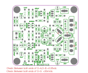
You can also connect two green 2mm low current leds antiparallel to the C5, the 330pF capacitor, in conjunction with the R4, the 3k3Ohm resistor, this rudimentary limiter works perfectly.
It is important to prevent rail-to-rail modulation of the output stage.
greetings,
HBt.

It is important to prevent rail-to-rail modulation of the output stage.
greetings,
HBt.
Last edited:
Kaneda SiC :
https://www.diyaudio.com/community/threads/semisouth-goes-dodo-what-now.222098/post-7233757
https://www.diyaudio.com/community/threads/semisouth-goes-dodo-what-now.222098/post-7452361
https://www.diyaudio.com/community/threads/semisouth-goes-dodo-what-now.222098/post-7453196
https://www.diyaudio.com/community/threads/semisouth-goes-dodo-what-now.222098/post-7732199
What is interesting is the gain structure between the stages.
The SiC Mosfets from Rohm have rather low transconductace (1S or less).
Most of the open loop gain has therefore to come from the first two stages.
And there is quite a bit more NFB compared to, say, the First Watt J2.
With +/-15V rails, it is not delivering a lot of power either.
1st Stage gain ~ 18x
2nd Stage gain ~ 16x
O/P Stage gain ~ 12x
CLG ~ 25x
NFB ~ 140 (43dB)
40~50dB NFB is quite typical Kaneda.
Compensation is required for the high positive tempco of the SiC MOSFETs.
Patrick
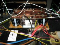
Today I replaced those big can capacitors, just finished.
First CD after that, yes the sound open up! Of course it need to break in. I added similar capacitor bank like Juma's and Kaneda amp having.
Thank you for the advise about the green LED.
I only have at home 3mm type if that fine I can test it later when I remove the PCBs from the heatsink.
Not much room around 330pF capacitor.
Also the PCB so delicate (small in size) I have to be very careful soldering and de-soldering components.
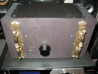
I have a small Class A amplifier case and I wanted something into it.
I pick this M Fidelity A1 amplifier. I read and heard a lot of good things about her.
Right now it has 56 000uF each rail.
First CD after that, yes the sound open up! Of course it need to break in. I added similar capacitor bank like Juma's and Kaneda amp having.
Thank you for the advise about the green LED.
I only have at home 3mm type if that fine I can test it later when I remove the PCBs from the heatsink.
Not much room around 330pF capacitor.
Also the PCB so delicate (small in size) I have to be very careful soldering and de-soldering components.
I have a small Class A amplifier case and I wanted something into it.
I pick this M Fidelity A1 amplifier. I read and heard a lot of good things about her.
Right now it has 56 000uF each rail.
Attachments
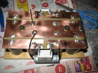
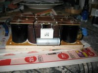
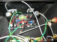
These is how the PCB looks like. It is about 80 X 75 MM, small size with skinny traces.
For a Class A amp it is a very bad PCB design!!
I would like to upgrade some parts like the BD139/140 to a Toshiba device. I have some original good quality Toshiba VAS transistors.
Because of that I afraid to de-solder anything!
Also instead the 2 X 1uF I used Wima 2 X 1.5uF WIMA capacitors.
Someone upgraded his original M Fidelity with Wima, I follow that.
Maybe I upgrade to 10uF Silmic or Nichicon MUSE (green). I am not a big fan of the Wima caps on the input.
Sometimes I use what I got at home.
You can see they left out the 4 piece of the 1N4148 diodes and also not much room to ad the 2PC of LED next to the 330pF capacitor.
By replacing the big can capacitors the sound definitely opened up! Almost like a different amplifier. Sound much better not that boring, clouded mid-bass anymore.
I need to run her at least 50 to 100 hours to burn in for better evaluation. ( to compare to the other amplifier). It is a promising amplifier, not bad at all.
Attachments
Patrick I think I will test the first SIC Kaneda from the list you posted.
That is close to the original Narsis Kaneda circuit, the one I built and started this thread.
I did modified the layout already for that.
I think I will test it with common non exotic parts to keep the cost down until I test her.
That is close to the original Narsis Kaneda circuit, the one I built and started this thread.
I did modified the layout already for that.
I think I will test it with common non exotic parts to keep the cost down until I test her.
Many thanks for the close up picture!!You can also connect two green 2mm low current leds antiparallel to the C5, the 330pF capacitor, in conjunction with the R4, the 3k3Ohm resistor, this rudimentary limiter works perfectly.
View attachment 1347198
It is a IV converter, not a power amp.Patrick I think I will test the first SIC Kaneda from the list you posted.
The K279 is.
Patrick
Patrick thanks for the warning!
It is way to similar to the Narsis Kaneda......... I already modified the layout for that🙄🤣.
The others are too complex for me to draw layout with the computers paint program or work on low rail voltage. To small amp........
Anyway I am very happy I built the Narsis K, it is a very nice sounding little amp.
I wanted to try something with SIC Fet, that would be my first SIC fet amp......
Greetings gabor
Last edited:
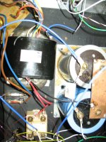
A1 the rest ofMany thanks for the close up picture!!
the missing Pictures.
It also looks wonderful and inspires me /and other to rebuild itAnyway I am very happy I built the Narsis K, it is a very nice sounding little amp.
😎
Kaneda designs are very popular in Japan, but vastly underrated outside Asia.
Having said that, the basic circuit topology has not changed in the last 40 years or more.
It has always between dual differential followed by (quasi) push-pull, with loop feedback.
Patrick
Having said that, the basic circuit topology has not changed in the last 40 years or more.
It has always between dual differential followed by (quasi) push-pull, with loop feedback.
Patrick
" ...followed by (quasi) push-pull... "
Not a trace of "quasi" (as in quasi-complementary) in this Kaneda design.
The output stage is driven by counter-phase signals (totem pole style).
See examples in First Watt F6 design and Elvee's Circlophone.
Not a trace of "quasi" (as in quasi-complementary) in this Kaneda design.
The output stage is driven by counter-phase signals (totem pole style).
See examples in First Watt F6 design and Elvee's Circlophone.
There is a French DIY forum similar to ours and Kaneda it is very popular there!Kaneda designs are very popular in Japan, but vastly underrated outside Asia.
Having said that, the basic circuit topology has not changed in the last 40 years or more.
Patrick
Time to time I visit that forum and read (with translator) some of their threads, builds etc.
I think because of Mr Jean Hiraga among French DIY-ers very very popular and Mr Jean Mark "(like the French Nelson Pass)".
Of course not as popular like in Japan.
The Narsis Kaneda circuit I found long time ago from a Japanese DIY-er website, he and his feedback about the amp inspired me to build it.
You can search 金田明彦 or 金田式.
Then use automatic translation to read.
It is very good these days, and you can understand 80%.
Patrick
Then use automatic translation to read.
It is very good these days, and you can understand 80%.
Patrick
- Home
- Amplifiers
- Solid State
- Narsis / Kaneda MosFET Amp built