
Very likely...........most probably a replacement device or his works are modified Kaneda's. 🤔
I wish I could open KiCAD files to see if there is a power board or just the input part and it needs to be hard wired?While scanning some of my downloaded KiCAD files (for reference), I found this one zipped folder, it contains 3 schematics in a whole KiCAD job files. The files I believe was shared by one member, he provided the link for downloads. It does contain one completed pcb lay out with gerbers included and one incomplete lay-out. The zipped files attached contains them all, (opens in KiCAD program).
The BJT version looks interesting to me, are these schematics a true Kaneda designs?
Also if there is 3 different input maybe just pick one not all 3 of them.
Very likely this is a Kaneda Class A amplifier topology.
I meet with that schematic on the net but never considered. I do have too many Class A amps to finish.......
Of course anyone interested more than welcome.... 🙂
I meet with that schematic on the net but never considered. I do have too many Class A amps to finish.......
Of course anyone interested more than welcome.... 🙂
Quite easy, download a copy of KiCAD and install. KiCAD is a free open source program available for Windows and Linux OS'es. Unzip the folder and open it in KiCAD, just point where the unzipped folder is located, KiCAD will automatically scan the files. Or another way is, after unzipping the folder right click on any file, a dialog box will appear. Find 'opens with' and point to KiCAD. I wish I could show you images on how it is done but right now I am away from my laptop. I am the 'chef of day 😄I wish I could open KiCAD files to see
Found the source link maybe you could PM him..
https://www.diyaudio.com/community/threads/kicad-kick-start.416550/
Attachments

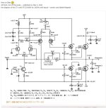
50W Class A published in La Revue de L’Audiophile. From Bonavolta link https://www.bonavolta.ch/hobby/en/audio/tp2788.htmWhile scanning some of my downloaded KiCAD files (for reference), I found this one zipped folder, it contains 3 schematics in a whole KiCAD job files. The files I believe was shared by one member, he provided the link for downloads. It does contain one completed pcb lay out with gerbers included and one incomplete lay-out. The zipped files attached contains them all, (opens in KiCAD program).
The BJT version looks interesting to me, are these schematics a true Kaneda designs?
Attachments

Last edited:
Schematic by Pierre Johannet published in "L'Audiophile"
Not every Double-Differential circuit is original Kaneda.
https://www.diyaudio.com/community/threads/kaneda-50w-class-a-amplifier.17178/post-3227431
https://www.diyaudio.com/community/threads/kaneda-50w-class-a-amplifier.17178/post-3227437
The picture also does not correspond to the link above (TP2788).
Maybe this one :
http://6bm8.lab.free.fr/Documentations/Revues/Audiophile/1977-1988/43/CLASSEA/CLASSEA.html
Patrick
Last edited:
Explanation for TP2788 / TP9634 :
"TP9634 was originally 2SA634/2SC1096, ....
The original outputs where 2SA627/2SD188 now discontinued. For TP2788 I have used 2SB686/2SD716 with no problems."
https://www.diyaudio.com/community/threads/hiraga-20w-class-a.193/post-1550
And it has a differential output stage with low rail voltages, unlike the picture above.
Patrick
Attachments
@EUVL
I was very impressed by your idea that you can get 2sk190 with 4x 2sk209. I want to make a Kaneda amplifier and it is difficult for me to get 2sk117. Can we create a 2sk117BL jfett using new generation jfets. There are currently jfets such as 2sk208-209-880 etc. LSK170 etc. You know better than me.
Which one do you recommend among Kaneda amplifiers? There are a few versions that I have chosen... Which one do you think is suitable?
Attachments


2SK209 is the SMD version of 2SK117.
But it has much lower dissipation.
I would not use it for more than 50mW.
The above schematics have a lot of voltage values given.
You can easily work out the current through a resistor using Ohm's law ( I=V/R).
If that resistor is in series with the JFET, it is safe to assume that they have the same current.
The power is simply P=V.I
If the JFET sees 50V and has a current of 2mA, then clearly 2SK209 will not do.
Using two in parallel doubles the capacitances.
So not direct replacement.
See also :
https://www.diyaudio.com/community/...-described-by-paul-kemble.220923/post-7797831
Patrick
Last edited:
- Home
- Amplifiers
- Solid State
- Narsis / Kaneda MosFET Amp built