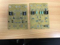
The boards take me back many years Jeff, as they are definitely "old school" without the solder mask, silk screen and gold plating.
The waiting list is now open. First come, first served.
For payment instructions, see: NAP250 amp boards & regulator boards
Remaining stock:
8 amp boards
8 inverted regulator boards
2 original regulator boards
Cheers,
Jeff.
For payment instructions, see: NAP250 amp boards & regulator boards
Remaining stock:
8 amp boards
8 inverted regulator boards
2 original regulator boards
Cheers,
Jeff.
Mine arrived in time for Christmas, thanks Jeff.
Looking forward to getting the components ordered up and starting.
Looking forward to getting the components ordered up and starting.
The original used a centre-tapped 40-0-40 of either 450VA or 500VA (opinions differ).
I'm using a 500VA twin secondary 0-40, 0-40.
Both used full-wave rectification; the centre-tapped transformer requires only 1/2 of each bridge rectifier for a rail (although one of the extra pairs was used to power the front-panel lights).
The twin secondary transformer will need both halves of each rectifier.
Cheers,
Jeff.
It is also possible to wire a twin secondary transformer to mimic a center-tapped one. This would allow using a pair of block rectifiers in a full-wave configuration as Naim did with the Olive-era NAP 250. Simply tie the 'low' output of one secondary winding to the high output of the other one. The block rectifiers may be 25Amp variety, and you can experiment with modern ones. For block-style rectifiers, I prefer the Vishay VS-26MB40A. The Vishay LVB2650 is another possibility, in an inline leaded package.
The original bulk PSU caps were somewhat under-rated for this duty and had to be replaced after 10 years, or they would start leaking excessively. I recommend using 80V or 100V caps for better longevity. The modern line to consider would be KEMET ALS70 series, such as ALS70A203KF100 or ALS70A363MF100.
The original bulk PSU caps were somewhat under-rated for this duty and had to be replaced after 10 years, or they would start leaking excessively. I recommend using 80V or 100V caps for better longevity. The modern line to consider would be KEMET ALS70 series, such as ALS70A203KF100 or ALS70A363MF100.
Remaining stock:
6 amp boards
4 inverted regulator boards
2 original regulator boards
Cheers,
Jeff.
6 amp boards
4 inverted regulator boards
2 original regulator boards
Cheers,
Jeff.
Excuse my ignorance, but I would appreciate clarification/diagram of what you are suggesting here.
Please see this link and look at the last schematic on the bottom of web page, is this what you are suggesting?
Thanks
Sajjad
Please see this link and look at the last schematic on the bottom of web page, is this what you are suggesting?
Thanks
Sajjad
The original used a centre-tapped 40-0-40 of either 450VA or 500VA (opinions differ).
I'm using a 500VA twin secondary 0-40, 0-40.
Both used full-wave rectification; the centre-tapped transformer requires only 1/2 of each bridge rectifier for a rail (although one of the extra pairs was used to power the front-panel lights).
The twin secondary transformer will need both halves of each rectifier.
Cheers,
Jeff.
Yes, "Diagram 3" on that page shows how to do it with twin (ie: non-centre-tapped) secondaries.
Yes, "Diagram 3" on that page shows how to do it with twin (ie: non-centre-tapped) secondaries.
Thank you
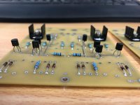
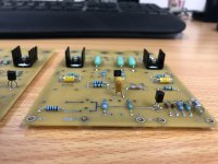
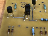
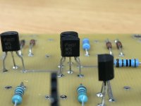
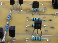
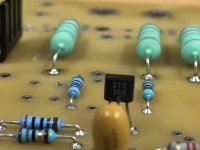
I have started to populate the boards with parts I already had. I am posting some pictures mainly due to anxiety about transistor and diode orientation as I am a novice. Please comment if you spot a problem.
Thanks
Sajjad
Thanks
Sajjad
Attachments
Hi Sajjad,
Looks good to me. Only comment I would have is to hold the transistor legs at their wide spot with some very small needle-nose pliers when you bend them so that you don't put any stress on them where they join the casing. (I use Xuron 450-TweezerNose pliers for this -- and many other things.)
Cheers,
Jeff.
[Edit: to double-check the diode orientations against the stuffing guide, the banded end always goes towards the square pad.]
Last edited:
Hi Sajjad,
Looks good to me. Only comment I would have is to hold the transistor legs at their wide spot with some very small needle-nose pliers when you bend them so that you don't put any stress on them where they join the casing. (I use Xuron 450-TweezerNose pliers for this -- and many other things.)
Cheers,
Jeff.
Thank you for checking and I appreciate it. I will order the pliers you mentioned, I did not know such a thing existed. I was using a forceps to bend legs😀.
Cheers
Sajjad
Jeff, I ended up here after perusing the thread on the ebay NAP140 boards, which seem like a lot of headache. Your boards seem like a much more interesting project.
Do you still have remaining stock to build an amp? If so I'll up for buying some boards. Thanks
Do you still have remaining stock to build an amp? If so I'll up for buying some boards. Thanks
- Home
- Group Buys
- NAP250 amp boards & regulator boards