few more questions
1- Amp boards power supply area has place for a jumper. what is best practice, should I just put a jumper or run 2 separate lines to power supply?
2- I cannot find 39pf PS capacitors even on ebay, any suggestions?
3- How important is to match the BC239C. I am using this but I do not have a multi-meter sensitive enough to detect the voltage, I have 4000 count multi-meter but probably need to invest in 60k count. So If I can avoid matching input pair it will save me a lot of hassle.
4- After assembling the NCC200 boards one could check the test points before mounting OP transistors, is that possible or necessary in these boards?
Thank you in anticipation
Sajjad
1) Best practice is probably two separate wires. Naim didn't do that, so I was curious and added the jumper so it could be tried out. Will you be able to hear the difference? I doubt it, to be honest.
2) I got some 39p styrene capacitors from Don Audio in Germany. However, they have a non-standard lead diameter, so the holes have to be drilled out a bit. If you're not a stickler for originality, 47p will work 99% as well. RS have them (with a "normal" lead diameter so no drilling required).
3) You'll read that some folks (including the NCC200 camp) think one of the 239s should have an hFE 10% higher than the other. I think that's bunk, but that's just my opinion. (It does appear to have been shared by Julian Vereker, though, as Naim didn't offset them either.) On the other hand, if a bunch of folks think the 10% mismatch sounds better, then that tells me that either (a) it doesn't really matter much, or (b) expectation bias is *really* strong.
That being said, I do think you want to match them (my batch of 20 showed over 100% in variation). I just don't think you need to be very fussy about it.
4) Yes, that check can be used on these boards too.
Cheers,
Jeff.
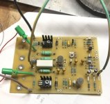
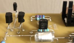
I used 39pf radial PS from an old tube amp and cheap connectors from my drawer. If everything works I may change to the ones suggested by Jeff.
First power up test without op transistors has been successful 🙂
Bias at minimum adjustment is acceptable (I hope) 😕
Now the task ahead is to drill holes for TO3. 🙄
Cheers
Sajj
First power up test without op transistors has been successful 🙂
Bias at minimum adjustment is acceptable (I hope) 😕
Now the task ahead is to drill holes for TO3. 🙄
Cheers
Sajj
Attachments
Last edited:
Hi Sajjad,
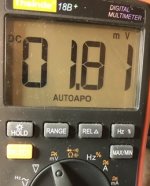
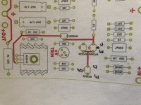
For that bias test you want to be measuring the voltage spread across the VBE spreader. What you're measuring between TP1 and TP2 is the voltage drop across the emitter resistors, which won't be meaningful without the output transistors in place.
(Note also that your meter is reading mV, not V.)
To do the other test connect your leads across the capacitor in front of the VBE spreader (TR5).
Are those 39p the rocket-shaped ones from TheStylusLady? I have some of those too. 🙂
OMG! Little knowledge is always dangerous!
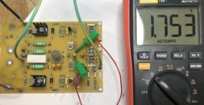
Thank you Jeff, I’ve corrected the leads as you suggested. Now on 47uf capacitor legs, I can still adjust the voltage.
You are spot on, these were bought from stylus lady, I had to make a u shape jumper to mount them.
Thanks
Sajj
Thank you Jeff, I’ve corrected the leads as you suggested. Now on 47uf capacitor legs, I can still adjust the voltage.
You are spot on, these were bought from stylus lady, I had to make a u shape jumper to mount them.
Thanks
Sajj
Attachments
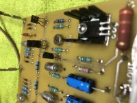
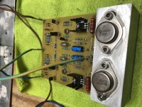
Huston, we have a problem.
After mounting the op transistors and checking for short circuit I powered on and mpsa56 have blown up on DBT.
Please guide me!!
Thanks
Sajjad
After mounting the op transistors and checking for short circuit I powered on and mpsa56 have blown up on DBT.
Please guide me!!
Thanks
Sajjad
Attachments
Hi Jeff,
Do you have a later version of the Inverted Schematic?
The one I have has NPN symbols for MPSA56 so I just wanted to make sure I'm getting the orientations correct.
Cheers!
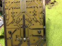
do you know if stuffing guide is replicating this error?
As per stuffing guide we are connecting 2 Emitters to one collector. Electronically
Should this be the right way or 2 collectors need to be connected to one Emitter?
Thanks
Sajjad
Attachments
Last edited:
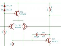
The collector of the CCS transistor should be tied to the emitters of the LTP transistors. So it looks like the boards (and the stuffing guide) are correct; just not the schematics.
But this doesn't explain Sajjad's problem. Which MPSA56 went? (And what does "DBT" mean?)
But this doesn't explain Sajjad's problem. Which MPSA56 went? (And what does "DBT" mean?)
The collector of the CCS transistor should be tied to the emitters of the LTP transistors. So it looks like the boards (and the stuffing guide) are correct; just not the schematics.
But this doesn't explain Sajjad's problem. Which MPSA56 went? (And what does "DBT" mean?)
DBT- dum bulb tester - it glows then dims and then bang
TR2, TR5 and TR7 blow each time
I’ve used a variac and negative side regulates power supply but just the positive side keeps blowing.
Thanks for confirming the boards are fine.
Sajjad
EDIT- I am using 2 x 40V ac Toroidal Transformer, 500VA with 2 bridge rectifiers and 2x33000 uf 63v capaciors final output is DC56v
Last edited:
You've got an A06 in TR7, not an A56, right?
yes that is correct.
Attachments
Last edited:
Crap. There's another error: there's supposed to be a 140ohm resistor between the rail and the emitter of the CCS transistor.
Try that and see if it works....
Try that and see if it works....
Yeah, I ran the simulation without that resistor and it feeds several watts into the MPSAs (which is never going to work).
Crap. There's another error: there's supposed to be a 140ohm resistor between the rail and the emitter of the CCS transistor.
Try that and see if it works....
Thank you Jeff for helping me. Can you please tell me exactly which two points need 140 ohm resistor?
Thanks
Sajjad
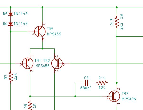
Here's a new copy of the schematic. Note the new R23 and R24 (which you can see in the LTSpice picture I posted earlier, but which somehow didn't make it into the Kicad version).

What you want to do is not insert the outside leg of the CCS transistors (TR5 and TR6), and instead put a 140 ohm resistor in the PCB hole and the other end of the resistor soldered to the leg of the transistor.
(This is a bit embarrassing, but I guess it is DIY. )
)
I haven't built my inverted regulators yet, but I can populate that part of one of my boards and take a snapshot if you'd rather have a picture to go off of....
What you want to do is not insert the outside leg of the CCS transistors (TR5 and TR6), and instead put a 140 ohm resistor in the PCB hole and the other end of the resistor soldered to the leg of the transistor.
(This is a bit embarrassing, but I guess it is DIY.
)I haven't built my inverted regulators yet, but I can populate that part of one of my boards and take a snapshot if you'd rather have a picture to go off of....
Attachments
Thank you so much, I’m looking for 140 ohm resistor but I don’t have it. I will use 150 ohm instead and report back.Here's a new copy of the schematic. Note the new R23 and R24 (which you can see in the LTSpice picture I posted earlier, but which somehow didn't make it into the Kicad version).
What you want to do is not insert the outside leg of the CCS transistors (TR5 and TR6), and instead put a 140 ohm resistor in the PCB hole and the other end of the resistor soldered to the leg of the transistor.
(This is a bit embarrassing, but I guess it is DIY.
I haven't built my inverted regulators yet, but I can populate that part of one of my boards and take a snapshot if you'd rather have a picture to go off of....
Thanks
Sajjad
- Home
- Group Buys
- NAP250 amp boards & regulator boards