
Julian Vereker (the founder of Naim and the original designer of the amp) thought not. However, they have been known to self-destruct if you run them without speaker wires attached (which also have some inductance and so act like a coil).
Personally I don't use one. I know others that do.
Personally I don't use one. I know others that do.
Very nice design! Are you willing to share the Gerbers pour le PCB ? ( as I am looking for PCB's for a Naim 140 I would send you two PCB's as I have to order minimum 5)
Best regards
Christoph
Best regards
Christoph
Last edited:
Member
Joined 2009
Paid Member
Is it possible to put semiconductors together for stable bias?
I know Naim relied on the enclosure for bias control which is less than ideal but it’s possible to have an inherently stable thermal design, as I have done so already:
TGM10 - based on NAIM by Julian Vereker
but I didn’t use TO-3 power devices which makes it more challenging. Maybe there’s a way to do it.
Very nice design! Are you willing to share the Gerbers pour le PCB ? ( as I am looking for PCB's for a Naim 140 I would send you two PCB's as I have to order minimum 5)
Best regards
Christoph
Hi Chris, if someday you order pcb s I am interested in buying 2 pcs.
Greetings from Basel 🙂
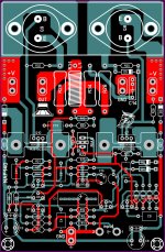
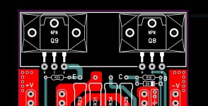
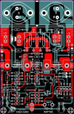
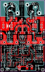
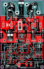
Better late than never....nobody? okay lol here is what I have so far I decide to add an option for TO-264 transistors anyway I'm just gonna documented here since this is a section for NAP 140 clones good day guys 🙂
There are good pics and details of the original Naim NAP 140 power supply and amplifier boards here: There's 2 version of NAP 140 PSU design? - Hi-Fi Corner - Naim Audio - Community.
These would suit several early Naim models but your posts feature the Avondale version, a modified clone with additional features, as you'd expect from someone trying to do better than the original product.
Is it possible to put semiconductors together for stable bias?
I know Naim relied on the enclosure for bias control which is less than ideal but it’s possible to have an inherently stable thermal design, as I have done so already:
TGM10 - based on NAIM by Julian Vereker
but I didn’t use TO-3 power devices which makes it more challenging. Maybe there’s a way to do it.
I'm gonna check on that sure 🙂
Better late than never....
There are good pics and details of the original Naim NAP 140 power supply and amplifier boards here: There's 2 version of NAP 140 PSU design? - Hi-Fi Corner - Naim Audio - Community.
These would suit several early Naim models but your posts feature the Avondale version, a modified clone with additional features, as you'd expect from someone trying to do better than the original product.
I'll take a look thank you 🙂
I would love to have a scanned image of the PCB of the NAP 140 and the PSU PCB's does some one have it? not from the eBay ones I mean the actual original PCB is some one can share I would really appreciated, by the way I don't have intentions or aim to sale noting only pure art PCB work and share ideas here if some one have the scanned image of the original PCB please PM me I'm a freak of vintage PCB designs 😛 thank you
Regards
Juan
Regards
Juan
Member
Joined 2009
Paid Member
there are some good images in the thread I linked but not bare boards. As the original is single sided it’s easy to copy.
Last edited:
Hi Juan.
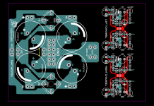
It's important to use good quality psu capacitors. Not all capacitors are the same. My rule of thumb is "the heavier the better", but mfrs never give the weight. I have used Mundorf MLytic AG with good results.
As you have modified the original amp circuit to have front-end rectification and smoothing (which I do not recommend), you are able to separate the front end psu traces from the power transistors. Have you considered building regulated supplies for the front ends? Naim have a front-end psu module now; I'm not sure whether they can be retro-fitted to a NAP-140 but they can on some NAP-250s.
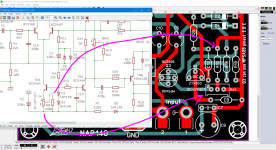
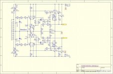
hi traderbam I was thinking to use the circuit from Ostripper capacitor multiplayer the current consumption is really low a few mA is just and idea that I have see image and schematic I'm thinking to add R7 10R is not on the layout PCB is a good idea? the TGM10 circuit looks interesting 🙂
Attachments
I see you are making a modified version of the original: Mongo-NAP? 🙂
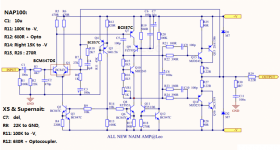
I think R7 is intended to reduce ground currents that might flow between the star ground of the amp and the ground of the equipment feeding the amp, which could modulate the input gnd voltage. The Naim does not use R7 and they expect a Naim pre-amp to drive the Naim power-amp, so they have control over the grounding arrangements.
I think R7 is intended to reduce ground currents that might flow between the star ground of the amp and the ground of the equipment feeding the amp, which could modulate the input gnd voltage. The Naim does not use R7 and they expect a Naim pre-amp to drive the Naim power-amp, so they have control over the grounding arrangements.
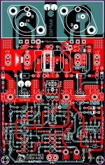
hi I add the R7 and R42 pot to adjusted dc offset also I change the R21 and C11 and the R25 and C12 orientation I use this schematic reference just a few things 🙂 MongoNap? good name 😛 lol
Attachments

Last edited:
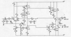
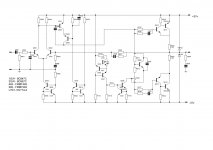
For reference I enclose some schematics I saved over time: one original NAP90 and recent amp designs reverse engenered by members of the Chinese forum:
Attachments

Guys,
I think i have been compromised. After i visited the psychologist.... i told her about this forum and what i think about it.
I also lied to her that i want to make a company based on this topology and then i said there is only one competitor,Sony lol.
But all i want is to help you and me understand what amplifiers are all about.
She liked the idea what i do in my garage but i feel she wanted to keep it secret. Maybe she is connected to naim company trought some religion... buddha for example that is present in estonia but has ties in england.
By compromised, i mean i have been poisoned, its when psychologist breaths into you... it did not work the first time, maybe cuz of the immune system.
she send a friend of mine that i havent met for a long time... he tried to take me to the wrong path... narcotics and alcohol. but i rejected it all.
I am little bit scared now😡
People are so bad this times.
Is it naim company that gave me these bad days ??
And u know guys its all about mendelejev table, the materials, solder joints, diodes in powersupply, wires and bending techniques. Wire diameter. the sound is not about fast transistor, transistor model, its a mass in both channels.
This concept is getting pretty easy for me and should be done right.
Last edited:
- Home
- Amplifiers
- Solid State
- NAP-140 Clone Amp Kit on eBay