Read the final bit of this if you have time. What an interesting way to do testing.
https://www.passdiy.com/pdf/citation.pdf
Nigel,
I tried that test few years ago and it didn't produce any meaningful results. I guess you really need to run the amplifier very hard and close to clipping to see distortion. Which is pointless to me - fact is that clipping amplifiers distort - no need to see that on a scope.
BTW, I would agree with Ian that the Naim schematic is not an original one. It may be tweaked, but not likely originally designed. May be that is the reason that nobody had ever been asked to remove it from certain websites. I've heard that Naim Audio, understandably so, are pretty nasty to copycats. My guess is that they simply don't have a case with this schematic... Or, may be they don't care, because they don't believe that anything made outside their factory can be good at all. 🙂
Last edited:
I wish Mr Morington West had sent the original. It would have been interesting to see the starting point.
I have a book from 1973 called Electronic circuits by David Casasent. No mention of LM 741 so I assume it's design was still secret as to internal parts. On p288 he describes the Motorola MC1530 . This seems to be a genius design. Rumor has it still made. It's designer seems to have been airbrushed out of history. What is really interesting is this <1965 design is all NPN. Some say it could still have advantages if converted into a power amp as it is unusually stable and wide bandwidth.
http://www.analog-innovations.com/SED/MC1530-TeachingExercise.pdf
Hi,
Not to move this away from the rather interesting points recently made here but given the topic title I wonder if I can ask for some simple wisdom.
I just built a pair of the Ebay clone boards, these are blue boards marked LJM/NAP 140 clone. Devices are a mix, BC546, 2SB647, 2SD667, 2N5551, 2N5401, 2SD669, 2SB649 and of course "Sanken" 2SC3858. Caps are all cheap floor sweeping grade I guess. So now the questions:
1. Will it work?
Built as supplied using the cheapy parts and the fake output transistors will it power up and make output noises relative to input noises? I hesitate to use the word music here 🙂
2. What are the must do's?
Just to make it function, if 1 above is a definite no. I'm not interested at this stage in which capacitors will sound better or which output devices will handle all my psu can provide, just absolutes to ensure safety of life, limb and pcb before 'puttin the fire to the wire!'
Thanks guys 🙂
At the time when Naim Audio was causing a new way of thinking in audio the real inspiration was a man called Stan Curtice. Here are his thoughts. He noticed how power supplies were the first things to be upgraded if wanting better sound. The Naim mostly is power supply differences as the technical difference between models. NAP 250 was very different compared with NAP 160 as far as sound is concerned. As far as I know mostly the same amp. The NAP 250 PSU looks like a separate extra power amp bolted on inside the box. All the extra power amp does is make up a fancy voltage regulator.
http://www.stancurtis.com/PDFs/HiFi Critic 4.pdf
http://www.stancurtis.com/PDFs/HiFi Critic 4.pdf
IME, the LJM boards are now the best low cost version available. You can buy fully finished and working versions from sellers like this one, so you know LJM PCBs are fine: 140 Classic Stereo Amplifier Board Full Assembled 2 Channel | eBay.....Devices are a mix, BC546, 2SB647, 2SD667, 2N5551, 2N5401, 2SD669, 2SB649 and of course "Sanken" 2SC3858. Caps are all cheap floor sweeping grade I guess. So now the questions....Will it work?....just absolutes to ensure safety of life, limb and pcb before 'puttin the fire to the wire!'.....
The problem that many builders found was the substitute parts in some suppliers' kits, genuine or not, did not match the pinouts or the overlay. Mainly, this was a problem for the input stage where pinouts for 2N5551 do not match BC546 or BC550C, for example. The parts you list seem to be the same as those fitted in the above example which is an interesting one, that also came with 2SC5171/A1930 drivers rather than TIP 41/42 that had been supplied in the past. Note the VAS transistors (Q4,6) 2SD667/B647 pinouts don't match preferred original ZTX653/753 either.
Personally, I think the BC546 is not ideal for the input stage and the original pair were BC550C anyway. Pinouts however, are marked on the board so check them. Capacitors supplied are possibly not great quality though a couple on some boards here are Elnas but ceramics > 100pF are not NPO types (check C8!). These are mostly multilayer types that should be fine but could eventually be replaced by film types. You could also fit genuine branded parts of the types supplied but either way, you should not have safety problems with this kit if your power supply is not more than the specified +/- 40V.
Last edited:
Thanks Ian, hopefully no fireworks then when I fire these up. They originate from the same source as the ones you mentioned.
I did not get a schematic diagram so can't easily identify the C8 you referenced. Only values are silk screened on the boards, not component designations. Is there an online schematic that shows these?
So far as the BC546 goes, it might stand replacement with the BC550C variant, seems this is the low noise version and C grade is the higher hfe part. I found BC547 at our local parts store but nothing more esoteric.
I have all the data sheets for the devices downloaded and checked for orientation. Junctions have all indicated the base at least is in the expected location. Next will be to make some volts measurements.
Thanks
Ian. How would you feel about BC337-25 as the input pair ? Looking them up recently they are 0.7 nV per root Hz which is about as low as low noise goes and must equal the BC550 of old. The gain is about 400 which makes for low DC offset especially if matched for gain and Vbe. Vceo is 45 V which is fine as the input stage has virtually no requirement to swing voltage. That is if the PSU is held to +/- 37 V typical or a regulated stage used up to the output transistors and drivers used. The BC337 is about 0.7 nV and the BC 546 1.3 nV. The BC550 was quoted as as 0.65 to 2.5 dB noise. The BC546 > 2 dB. The BC337 is a good substitute for BC550 and the BC 546 has a better voltage safety margin. I dare say if non destructively tested some BC337 could be selected for higher voltage. As far as I know that's exactly what the transistor makers do. That is test them from a high voltage ultra low current PSU. The voltage is advanced until they collapse. I dare say some will go to 80 V. The reason BC337 is low noise is that it is designed to allow moderate current flow. Rbb- is very low. The gain is surprisingly high considering that. Thus a universal device somewhat better than any op amp. This would mean a discreet op amp could be made from it. The Naim power amp is a discreet op amp. The transistors I would recommend further up the circuit would be MPSA42 and 92. These are much like 2N5551 and 5401 with surprisingly low Cob.
The very best op amps in the world fight hard to equal BC 546 so that is not too bad. The common place NE5532 at least twice as noisy.
Looking at the kit as offered, it is a far cry from the original. I would call it the last outpost of Quasi Complimentary amplifiers and the inspiration is Naim.
Ian, as you have said many times this section is for people new to electronics. I hope maybe one day we gang together and improve this amp. I learned age four from my dad. He never made any allowance for my age. Mostly I understood.
Ask your supplier of the PCB for the schematic.
You cannot be expected to successfully assemble a PCB without the correct schematic.
If they refuse to supply, demand your money be returned and compensation for the wasted postage to you and back again. Report to Ebay and to PayPal.
You cannot be expected to successfully assemble a PCB without the correct schematic.
If they refuse to supply, demand your money be returned and compensation for the wasted postage to you and back again. Report to Ebay and to PayPal.
It's a good point but they do say in their ad that no schematic is provided. Assembly is based on the values printed on the pcb. Maybe I need to draw it out myself, not too difficult, might give it a go tonight.
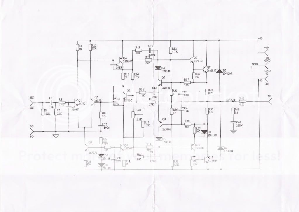
Guys, if you look at the Ebay sale item I linked, there are 4 thumbnail images on the left side. One is the schematic - admittedly difficult to read, even on a 24" widescreen. However, you will also find the same schematic earlier in this thread if you read it, or just look at the pictures if that is all too difficult. You will also find those transistor Q numbers are the same as the TR numbers on the original Naim schematic. Read the thread - see how much info is already here! 😉
Yeah, you're right. I looked at the link, didn't get a supersize version of the schematic though, just a 100 pixel thumbnail size job, totally unreadable 🙂 Need to search back through the thread for the schematics, seems there have been various versions. Maybe needs a Naim (and wannabe) schematics thread 🙂
A quick search and I've found where Ian posted the generic schematic at post #1159. Unfortunately this seems to be a broken link so the image does not display 🙁 Oh well more digging.
A quick search and I've found where Ian posted the generic schematic at post #1159. Unfortunately this seems to be a broken link so the image does not display 🙁 Oh well more digging.
Last edited:
Look at post 1049 then. That is for the same kit, supplied in 2012. Some transistor types have altered but surely you already are aware what has changed, like the input pair Q1 & Q2 and the drivers Q9 & Q10?
Last edited:
Guys, hello.
I Have a question about regulating Naim H-140 frontend. Looked it all up, everything is set... but still, not sure which transformer to choose for the frontend regulated voltage ? LM317T and LM337 will be used and voltage will be set to 44V(BC550B transistors have break down voltage at 45V)
Output will get 2V lower, means 42V unregulated, only smoothed with caps. bank.
Few tought's has crossed the mind, came up with the 50VA 2x34V Transformer which will have unregulated voltage about 48V from 235-236AC Voltage outlet. If i will regulate it all the way down to 44V, leaving some headroom for 230V+/- 10% outlets, good idea ? Will there be lots of heat on "LM317/LM337" regulators ? Every H-140 naim board will get seperate regulators, totalling up to 4 regulators for stereo configuration.
This means max current could be ~60mA on each regulator when everything is biased and working ?
Need some advise here guys !
Thanks.
Using LM317/337 at their maximum differential is unwise. The maximum allowable supply voltage is 40V with a minimum drop of 3V but exceeding this will be all too easy, particularly if you try to use something as large or larger than a common 30VAC transformer. https://www.fairchildsemi.com/datasheets/LM/LM317.pdf
Use a capacitance multiplier rather than a linear regulator and minimize the loss of output voltage swing too. A simple, 1 transistor mutiplier using a BC547 etc will be sufficient for the front end where current is only around 10 mA. These designs are for higher current with darlington transistors but the same principles apply:
The Class-A Amplifier Site - The Capacitance Multiplier
Edit: note that the maximum rail supply voltage with the standard parts will be +/- 40V. Exceeding that requires a redesign to something much larger where H140 or NAP140 will be found too basic for the expected performance. Start with a board and design capable of double the power if you want to increase the supply voltages successfully. You will need to raise component ratings too, so the cheaper solution would be start out with a larger design.
Last edited:
Guys, hello.
I Have a question about regulating Naim H-140 frontend. Looked it all up, everything is set... but still, not sure which transformer to choose for the frontend regulated voltage ? LM317T and LM337 will be used and voltage will be set to 44V(BC550B transistors have break down voltage at 45V)
Output will get 2V lower, means 42V unregulated, only smoothed with caps. bank.
If you really insist on regulation, instead of using two transformers, you could use regulated lines from the output 42V unregulated.
With two transformers you'll have very complex grounding and most likely will introduce noise and distortion, unless you know very well what you're doing. Much simpler and effective is to regulate to about 33-34V from the 42V and to use that section for the front end. It will also give you some room for fluctuating line voltages.
The thing is that the 317/337 are rated to about 40V, and 42V is kind of borderline. You can use the high voltage version LM317HV, although I'm not sure if HV version exist for the negative LM337.
Even with this simpler modification you'll have changed grounding arrangement and I can not guarantee better final results. I believe that in this (and any other amp) the grounding is of same importance as the "signal" path. Actually, everything is signal path. The grounding path included.
Instead of regulating you may want to do the capacitance multiplier recommended by Ian. I have tried that and didn't like the sound, but most people say it's a worthy mod.
Regards
- Home
- Amplifiers
- Solid State
- NAP-140 Clone Amp Kit on eBay