
Removed several off-topic and political posts. Please refrain from making posts not on topic, or the thread will disappear for good and infractions shall be handed out for your efforts.
Basically, what i want is you guys to work on that schematic and try to understand why it excites at a certain point and how to maintain in that "super transparency" region for a longer periods of time.
It might be easier then you think and it is always temperature dependent scenario.
It has something to do with the harmonic profiles, matching them from PSU to AMP for excitment.
It is possible with ZTX453, ztx 553, ztx 752, ztx 652, ztx 753 and 653, A1145 and 2SC2705.
Only the first input transistor must be LOW NOISE, BC550 is preferable.
There is no need for preamp. There is also no need for "modifications", simpler is always better, less is more.
And, i think we need that DIODE + inductor in the amplifier case. 😀 (it is so funny to think that this is stupid... but its not lol😀).
This has a purpose, if you understand the component behaviour under different temperature regions than you will understand why we need some oscillation near amplifier boards.
....
It's been clear for many years that the ZTX series transistor types always specified in NAP and Nait series models, have unusually high Cob (output capacitance) for a "transimpedance" or voltage" amplifier and its current sink. If an engineer were to design the generic Naim amplifier circuit back in 1970 or even now, they would most likely use another type of transistor with low capacitance to gain a lower distortion figure. That should sound better, right?
Wrong! It happens that many people like to hear certain distortions and will pay more money to hear them in their "audiophile" types of amplifier. For example, have you never wondered what Naim's "PRaT" is all about? More to the point; what distortions do you seek in your own experiments and how far from Naim sound are you already? As you have no reference, you can't know that and neither can anyone else.
If a designer is not clear about the principles involved in transistor amplifiers, they are likely to make mistakes by choosing semis from only their their basic specifications. In my view, this was a very fortunate mistake by JV because the products proved to sound very nice to many people who auditioned them at the time. The proof that Naim have long known about this particular "error", is that these types of transistors were still used exclusively in original NAP and Nait series models for as long as they were in production. Every wonder why?
As a comment, I've listened to many cheap clone kits assembled by kids, audio enthusiasts and guys like me who have the time and interest to DIY their audio. The kits all came with "better" VAS transistors, like 2N5551/5401, D667/B647, A1145/C2705 but alas, none of them sounded great and had very little PRaT. However, I don't believe that is the only mechanism in play. Nothing in audio electronics is ever that simple but I think it's the most significant one.
When experimenting, one has to think and ask why something that concerns you is so before just trying new and different ideas to change it. That often leads nowhere but around in circles. Circuits of mine and designs that I thought sounded great ten years ago have changed or rather, I have changed and I don't like them now. How can this be?
I'm sure that it points to a bigger problem that will probably affect all of us at some time. Meanwhile, lets get others, friends maybe, to listen too and see if they agree with your findings. Unless you are already adept at electronic design and have wide experience with top quality audio, it will always help to have agreement or not and comments to consider with your own findings.
Really? In the course of trying a few modifications requested by the owner of an old NAP110, I replaced the ZTX types with, as I recall, 2SC2911/2SA2902 (just a few pF Cob). Poof! very few sound effects at all. In fact, not so good to listen to.
The amplifier had similar to original voltage gain at 20kHz and a sinewave under load still looked very clean. Before tinkering though, I actually heard more effects than just the PRaT there. There were also splashy, low level sounds from the striking of tiny bells, cymbals, even breaking glass for example. You can also try other transistor pairs better suited to VAS and I think you'll find all the obvious sound effects more or less track with the capacitance (it's a staggering 30pF in the case of ZTX 652/3, 752,3. I think that's a uniquely hign Cob for the application. It may not prove the source of the effect but it's reasonable to conclude that there's a connection between the effects and the types of semi. Since then, I've checked this a few more times but not as thoroughly as there's been no need. Other types used less often by Naim were ZTX 452/552 which had only half that capacitance and appear to be in a similar class to BC639/640.
Given the task to design a voltage/transimpedance amplifier and its current sink or source for low audio distortion, what transistor characteristics would you select for the roles? Would it be the conventional low capacitance types or a fat capacitance type? Alternatively, would it not matter at all and the guys who design the amps and spec. the semis have had the VAS linearity thing wrong all these years?
Yes 🙂Really? In the course of trying a few modifications requested by the owner of an old NAP110, I replaced the ZTX types with, as I recall, 2SC2911/2SA2902 (just a few pF Cob). Poof! very few sound effects at all. In fact, not so good to listen to.
Yes 🙂It may not prove the source of the effect but it's reasonable to conclude that there's a connection between the effects and the types of semi.
That’s not the right question. 😎Given the task to design a voltage/transimpedance amplifier and its current sink or source for low audio distortion, what transistor characteristics would you select for the roles? Would it be the conventional low capacitance types or a fat capacitance type?
Wouldn’t surprise me 😉Alternatively, would it not matter at all and the guys who design the amps and spec. the semis have had the VAS linearity thing wrong all these years?
-NCC200 schematic 220R+1N4004 series; for decrease voltage. Can we use zener instead of resistance&diode? why?
-NAP250, NCC200 uses 40volts, so decrease in voltage changes the pre stage(Tr1,2, VAS) voltage. Do we use for example 43 volts for stay 40v for pre stage?
-Second question is, what is the TR1&TR2's Hfe ratio? There are many theory 🙂 1:1 or not?
-NAP250, NCC200 uses 40volts, so decrease in voltage changes the pre stage(Tr1,2, VAS) voltage. Do we use for example 43 volts for stay 40v for pre stage?
-Second question is, what is the TR1&TR2's Hfe ratio? There are many theory 🙂 1:1 or not?
Basically, what i want is you guys to work on that schematic and try to understand why it excites at a certain point and how to maintain in that "super transparency" region for a longer periods of time.
It might be easier then you think and it is always temperature dependent scenario.
It has something to do with the harmonic profiles, matching them from PSU to AMP for excitment.
It is possible with ZTX453, ztx 553, ztx 752, ztx 652, ztx 753 and 653, A1145 and 2SC2705.
Only the first input transistor must be LOW NOISE, BC550 is preferable.
There is no need for preamp. There is also no need for "modifications", simpler is always better, less is more.
And, i think we need that DIODE + inductor in the amplifier case. 😀 (it is so funny to think that this is stupid... but its not lol😀).
This has a purpose, if you understand the component behaviour under different temperature regions than you will understand why we need some oscillation near amplifier boards.
....
Hi Rensli, can you tell me the replacemente for BC550.
Regards
Hi kandimba. rensli advised that he had to leave the forum. Perhaps I can help with a question first and then some possibilities for you to consider. The question is; what is your preferred buying option? Is it from platform sellers at Ebay, Ali Express, Amazon etc. or from bona fide distributors like Farnell, RS components, TLE, Digi-key, Mouser etc?
The first option usually means very cheap, generic parts from China with no guarantee that they will have the same quality as original specification parts. They will likely work OK but lack good performance in the key areas of gain and low noise. Genuine parts, particularly the old TO92 thru-hole style semis like BC550, are expensive when bought in small quantity so you need to be careful where you shop and the quantity.
If you are determined to shop cheaply, try another type like C1815 and its complement A1015 that are often very cheap in quantities of 25-100 or even 1000. You will find they don't have particularly high gain (hFE) but with enough parts to select from, that can be consistently high enough for the input stage of any well-designed power amplifier. There are also genuine products from Onsemi, like KSC1845/KSA992 that are excellent transistors for the application but I suspect rensli was exploiting the faults of his particular brand BC550 as much as their quality. He seldom commented on his sources so I can only guess they were generic products too.
There is much more to the story of Chinese copies but you probably realise that the original quality parts are now virtually obsolete, replaced by tiny, SMD equivalent types. The remaining TO92 products will soon disappear too or become very expensive.
Last edited:
1.The diodes are for reverse voltage protection and isolation, not for regulating it. The resistors reduce the voltage so that the supply voltages to the front end of the amplifier do not exceed +/-40V because that is the safe limit for the ZTX653/753 voltage amplifier transistors. It's possible to reduce that voltage in more controlled ways but since the current demand there is constant, resistance alone is apparently sufficient. You might notice that the Naim NAP250 design doesn't use these diodes or resistors but the power supply for the whole amplifier is limited to a nominal +/- 40VDC.-NCC200 schematic 220R+1N4004 series; for decrease voltage. Can we use zener instead of resistance&diode? why?
-NAP250, NCC200 uses 40volts, so decrease in voltage changes the pre stage(Tr1,2, VAS) voltage. Do we use for example 43 volts for stay 40v for pre stage?
-Second question is, what is the TR1&TR2's Hfe ratio? There are many theory 🙂 1:1 or not?
2.TR1,2 are tested for hFE within specificification but matched on test for the DC offset voltage measured at the amplifier output. The amplifiers are built in batches, so that once a (mis)match is made, other amplifiers will (mis)match similarly. However, building amplifiers one at a time from random parts will likely mean different results for each amplifier and every pair will need to be matched accordingly. The difficult part of matching is heat - even the heat of your hands is enough to cause the hFE to go wild, so avoid touching the semis. Note: by matched, I just mean chosen according to the lowest resulting offset voltage, as measured on test.
Standard topology reasons
It would be good to repost the related schematic but:
The diode, and the following 100uF caps maintain the LTP current for a short time after powering down, which reduces the resulting pop in the output. Otherwise the VAS CCS would produce a big negative pulse when the VAS shuts down. And, these, in combination with the resistor also reduce the power supply ripple to the IPS, both ~120Hz and supply droop feedback.
Balancing the LTP can be achieved in several ways besides matching transistors, but I can't say they all satisfy the "magic" sound you may be looking for.
(1) The schematic I see has no current mirror between the LTP and VAS so the base resistor has to be chosen so that half the LTP current produces ~0.65V plus any VAS degen resistor voltage for the VAS base. Generally that means it should be 2x the emitter resistor of the LTP CCS. You could tweak either of these resistors.
(2) You will note that the total bias resistance at the bases of the positive and negative inputs is very close if not the same. ie 27K =24k+3K I would move the 24K to the other side of the 3K and make it 27K, a match for the 27k feedback resistor, and then the 3K could be a smaller value, not part of the DC bias. But perhaps a small offset is not really a problem.
(3) And finally the 100 Ohm LTP degeneration resistors can be offset to balance the LTP. Using a pot instead of two resistors for offset adjustment is common although there should be a fixed resistor bypass so that pot slider open does not result in a huge DC output.
The collector resistor on the negative side of the LTP is redundant at best, and potentially contributes stability problems by unnecessarily compromising the phase margin. But then this amp has a "magic" sound for which you may feel that resistor is import.
-NCC200 schematic 220R+1N4004 series; for decrease voltage. Can we use zener instead of resistance&diode? why?
-NAP250, NCC200 uses 40volts, so decrease in voltage changes the pre stage(Tr1,2, VAS) voltage. Do we use for example 43 volts for stay 40v for pre stage?
-Second question is, what is the TR1&TR2's Hfe ratio? There are many theory 🙂 1:1 or not?
It would be good to repost the related schematic but:
The diode, and the following 100uF caps maintain the LTP current for a short time after powering down, which reduces the resulting pop in the output. Otherwise the VAS CCS would produce a big negative pulse when the VAS shuts down. And, these, in combination with the resistor also reduce the power supply ripple to the IPS, both ~120Hz and supply droop feedback.
Balancing the LTP can be achieved in several ways besides matching transistors, but I can't say they all satisfy the "magic" sound you may be looking for.
(1) The schematic I see has no current mirror between the LTP and VAS so the base resistor has to be chosen so that half the LTP current produces ~0.65V plus any VAS degen resistor voltage for the VAS base. Generally that means it should be 2x the emitter resistor of the LTP CCS. You could tweak either of these resistors.
(2) You will note that the total bias resistance at the bases of the positive and negative inputs is very close if not the same. ie 27K =24k+3K I would move the 24K to the other side of the 3K and make it 27K, a match for the 27k feedback resistor, and then the 3K could be a smaller value, not part of the DC bias. But perhaps a small offset is not really a problem.
(3) And finally the 100 Ohm LTP degeneration resistors can be offset to balance the LTP. Using a pot instead of two resistors for offset adjustment is common although there should be a fixed resistor bypass so that pot slider open does not result in a huge DC output.
The collector resistor on the negative side of the LTP is redundant at best, and potentially contributes stability problems by unnecessarily compromising the phase margin. But then this amp has a "magic" sound for which you may feel that resistor is import.

BTW, I should have said that there is already guidance on the NCC200 schematic which states that the hFE of TR1 should be higher than TR2. It doesn't indicate how much higher but with genuine BC546, BC550 or C1815, I wouldn't expect there to be a great difference in any small purchase quantity of parts and anything that measures less than say, 30mV is fine. The offset doesn't need to be zero, though some people seem to think it should be for their own bragging rights and reasons. A tiny number <10mV wouldn't be all that stable as the amplifier warms up anyway.
schematic link: Avondale NCC200 mod | Page 3 | pink fish media
schematic link: Avondale NCC200 mod | Page 3 | pink fish media
Last edited:
All valid points.
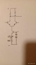
I find though that the easiest way to control offset is to add a trimmer in the resistor of the LTP current source. Normally I'd put about 400 ohms standard resistor and some 250 ohms multi-turn trimmer in series.
However, perfect offset doesn't mean perfectly balanced LTP currents in this circuit. But that's not the aim here and is just one of the many tricks that one has to try in order to get the "Naim sound". My personal preference is for slightly negative offset. Some -10 to -15mV.
Do you mind posting a picture or a hand drawn schematic for novices like me to try and replicate what you did?
Many Thanks
Many Thanks
Hi kandimba. rensli advised that he had to leave the forum. Perhaps I can help with a question first and then some possibilities for you to consider. The question is; what is your preferred buying option? Is it from platform sellers at Ebay, Ali Express, Amazon etc. or from bona fide distributors like Farnell, RS components, TLE, Digi-key, Mouser etc?
The first option usually means very cheap, generic parts from China with no guarantee that they will have the same quality as original specification parts. They will likely work OK but lack good performance in the key areas of gain and low noise. Genuine parts, particularly the old TO92 thru-hole style semis like BC550, are expensive when bought in small quantity so you need to be careful where you shop and the quantity.
If you are determined to shop cheaply, try another type like C1815 and its complement A1015 that are often very cheap in quantities of 25-100 or even 1000. You will find they don't have particularly high gain (hFE) but with enough parts to select from, that can be consistently high enough for the input stage of any well-designed power amplifier. There are also genuine products from Onsemi, like KSC1845/KSA992 that are excellent transistors for the application but I suspect rensli was exploiting the faults of his particular brand BC550 as much as their quality. He seldom commented on his sources so I can only guess they were generic products too.
There is much more to the story of Chinese copies but you probably realise that the original quality parts are now virtually obsolete, replaced by tiny, SMD equivalent types. The remaining TO92 products will soon disappear too or become very expensive.
Hi Ian Finch, thanks for your words.
Regards
I don't know there is how much difference between with Naim &NCC, in the forum somebody has written that in Naim's measured TR1&TR2's Hfe almost the same.BTW, I should have said that there is already guidance on the NCC200 schematic which states that the hFE of TR1 should be higher than TR2. It doesn't indicate how much higher but with genuine BC546, BC550 or C1815, I wouldn't expect there to be a great difference in any small purchase quantity of parts and anything that measures less than say, 30mV is fine. The offset doesn't need to be zero, though some people seem to think it should be for their own bragging rights and reasons. A tiny number <10mV wouldn't be all that stable as the amplifier warms up anyway.
schematic link: Avondale NCC200 mod | Page 3 | pink fish media
- Home
- Amplifiers
- Solid State
- NAP-140 Clone Amp Kit on eBay