They are all from the output of the regulators and you would expect all of them to have near zero ripple across them. Remember the meter only shows part of what is going on, the 25 volt rail may actually be a bit cleaner than the 45 volt rail in terms of noise as well as ripple.
Also (just for interest) see what your meter shows across those caps when you switch the amp off. It should show 0.00 but does it?
Also (just for interest) see what your meter shows across those caps when you switch the amp off. It should show 0.00 but does it?
I will check what happens when I turn it off.
But to my question above - I meant the DC voltages. So expecting same DC across the two red and two green ones, respectively. Trying to understand the schematic and learn 🙂
Also: I plan to acquire a scope. I can see I need one 🙂 I can probably score an old one from work.
Anything to look for? What does it need to be able to do?
Last edited:
What voltages are you actually getting? They should be within a volt or two of the nominal -/+ 25 and 45 volt.
This - but that is “red - green - red - green”.What I measure:
C810: 47.9 V DC, <0.5 mV AC
C811: 48.4 V DC, <0.5 mV AC
C819: 26.4 V DC, <0.5 mV AC
C818: 25.8 V DC, <0.5 mV AC
I was expecting similar at red and red, green and green, respectively?
This I why I ask how to interpret the schematic and the position of the components in relation to ground and voltage indications on the schematic 🙂
Do you mean the 0,1uF ones?The output of the regulators need only the small value caps shown.
Unfortunately I cannot agree here - the vast majority of the amplifier schematics that I have skimmed has typically 47 to 100uF caps on the regulator outputs (some manufacturers in some models go even to 470 or 1000uF).
Even NAD has these in other models:
216:
c320:
This - but that is “red - green - red - green”.
I see what you mean. It is possible the diagram references are wrong. Keep your black meter lead on ground at all times and measure to the regulator output transistors directly or locate other points on the circuit that the regulated voltages appear.
Measuring at the destinations is probably safer. Check the +45 and -45 are here.
And that the +25 and -25 are here:
Do you mean the 0,1uF ones?
Unfortunately I cannot agree here - the vast majority of the amplifier schematics that I have skimmed has typically 47 to 100uF caps on the regulator outputs (some manufacturers in some models go even to 470 or 1000uF).
I did mean the 0.1uF's That is all that is needed for stability.
If the current draw varies a lot then the designer has to decide whether more uF is beneficial or not. Higher values can inhibit the ability of a regulator to respond rapidly to change but on the other hand can smooth out those differences so changes in output level are less abrupt when they occur.
The 0.1uF 25 volt rails I imagine see constant current from the class A preamp stages. There will be no signal induced ripple there.
The 45 volt rails supply the driver stages of the power amp and so I can see a reason for higher values on the 45 volt rails if signal induced ripple is present and superimposed on the rail. Its always compromise. Big caps are cheaper than designing a better regulator with a low output impedance across a wide frequency range.
So since there "is nothing to regulate actively" (current draw is constant, mains voltage fluctuations are slow) then no harm will be done when adding e.g. 100uF on these rails and checking out their effect on hum?Higher values can inhibit the ability of a regulator to respond rapidly to change but on the other hand can smooth out those differences so changes in output level are less abrupt when they occur.
The 0.1uF 25 volt rails I imagine see constant current from the class A preamp stages. There will be no signal induced ripple there.
Actually it would be good to know if the hum frequency is 50 or 100Hz - both are possible.
No harm will be done adding caps as a test.
Yes.Actually it would be good to know if the hum frequency is 50 or 100Hz - both are possible.
you may find the hum is not the amp.There is no easy way to say this but many design aspects of the NAD are poor with excess heat generation from some areas being one of them. Regulator transistors can run very hot up to the point that the solder can start to crack around the leads and the series pass transistors (the ones that get hot) can suffer intermittent failures.
While the NAD's can and do sound good, the design and build quality is ....... (add your own words here 😉)
I have hadmany of these 3140's, and other nads(as @Mooly ) will vouch for lol, and the hum was a result of it being too near a mains source, normal LED'S, a lamp etc.
Nads do suffer this aspect, and you could get 3 models the same, and only one will hum, its just the way they are.
I had one of these and took it down stairs away from all other sources, and the hum went away, whcih proved the point.

In that case the hum should have been 50 Hz?I had one of these and took it down stairs away from all other sources, and the hum went away, whcih proved the point.
did you resolve this?In that case the hum should have been 50 Hz?
Sorry - missed some notifications apparently.
First, thank you @poundy for the better schematic - brilliant 🙂
Next: went to a guy with a scope yesterday. Still a DIY guy, but more experienced.
The hum totally disappears when engaging "low level" button, maybe we can use the better schematic to find out why.
First, thank you @poundy for the better schematic - brilliant 🙂
Next: went to a guy with a scope yesterday. Still a DIY guy, but more experienced.
- We confirmed it was 50 Hz and coming from the pre-amp.
- It appeared to be present already at the volume inputs
- It appeared to be present at volume ground - so in both channels. Is this meaningful?
The hum totally disappears when engaging "low level" button, maybe we can use the better schematic to find out why.
Yes - also a different house 🙂did you try it from another mains source and move it away from any other electrical equipment
All caps are replaced. Also, that looks like specific to the phono amp? I have it irrespective of source.I had a buzz and hum with one of these once.check these 2 caps out, thats what solved mine
So trying to dig further - as the “low level” switch makes the hum disappear completely, that is a starting point.Sorry - missed some notifications apparently.
First, thank you @poundy for the better schematic - brilliant 🙂
Next: went to a guy with a scope yesterday. Still a DIY guy, but more experienced.
We did not find the source, he now has the amp and will dig into it further. The better schematic will definitely help!
- We confirmed it was 50 Hz and coming from the pre-amp.
- It appeared to be present already at the volume inputs
- It appeared to be present at volume ground - so in both channels. Is this meaningful?
The hum totally disappears when engaging "low level" button, maybe we can use the better schematic to find out why.
What does it do with the signal? I.e. what is the signal path when switch is disengaged and engaged, respectively?
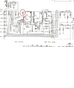
It is Sw7 marked in red.

It is a simple resistive attenuator.
The switch puts the 150 ohm in circuit so the signal taken from what is now the junction of a 1k5 and 150 ohm which gives a -20db reduction in voltage. So if that seems to remove the hum it is telling you the hum is getting in before that point.
The switch puts the 150 ohm in circuit so the signal taken from what is now the junction of a 1k5 and 150 ohm which gives a -20db reduction in voltage. So if that seems to remove the hum it is telling you the hum is getting in before that point.
- Home
- Amplifiers
- Solid State
- NAD 3140 ghost capacitor, hum problem & VU meter