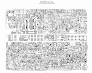
Is the 25 V rails the 25 volt output from the regulator? And is this found in area 7 in this picture (top right)?
I assume the 25 V “rails” are the 25 volt used throughout the amplifier, or?
Area 7 was totally “burnt” due to the power dissipating resistors, the capacitors there had lost their plastic etc.
I assume the 25 V “rails” are the 25 volt used throughout the amplifier, or?
Area 7 was totally “burnt” due to the power dissipating resistors, the capacitors there had lost their plastic etc.
Attachments


Thank you - as described above all caps are replaced (yesterday was the four large filter caps).
A lot of caps were way out of spec, but the four large ones were actually ok even though they bulged on top.
The area 7 had been rather hot (there are some large resistors and the adjacent components are insulated to protect them. Could there be something else wrong there, in addition to bad caps?
Is the “regulator” not the part that makes the correct voltages? And a source for noise?
So what can I do to check for “ripple”?
Last edited:
Check that all voltages are correct and stable. The regulated rails should not vary over time. To check for ripple, a scope is best. Put in on ac coupling and check the power supply rails for remains of the mains ac.
Sometimes a multimeter on ac can be used as well, provided it blocks dc on the ac settings (cheap ones often do not). Otherwise place a capacitor of a few uf in series with one of the leads. You're looking for ac in the mV range.
Hum can also come from a missing or bad ground connection somewhere. You may want to doublecheck you didn't miss anything on the reassembly.
The area 7 had been rather hot (there are some large resistors and the adjacent components are insulated to protect them. Could there be something else wrong there, in addition to bad caps?
There is no easy way to say this but many design aspects of the NAD are poor with excess heat generation from some areas being one of them. Regulator transistors can run very hot up to the point that the solder can start to crack around the leads and the series pass transistors (the ones that get hot) can suffer intermittent failures.
While the NAD's can and do sound good, the design and build quality is ....... (add your own words here 😉)
Super - thank you 🙏Check that all voltages are correct and stable. The regulated rails should not vary over time. To check for ripple, a scope is best. Put in on ac coupling and check the power supply rails for remains of the mains ac.
Sometimes a multimeter on ac can be used as well, provided it blocks dc on the ac settings (cheap ones often do not). Otherwise place a capacitor of a few uf in series with one of the leads. You're looking for ac in the mV range.
Hum can also come from a missing or bad ground connection somewhere. You may want to doublecheck you didn't miss anything on the reassembly.
My Fluke 177 can measure AC ripple according to MS Co-pilot.
I will try this and revert.
I can locate the caps in question and they were all replaced.
Next step: where do I measure the rail voltages/AC ripple? Included is the layout that is easiest for me to understand (the schematics are less easy to translate to real-world where-is-what 🙂 )
Attachments
Last edited:
Update:These are the four regulated rails and the main caps that need checking but in reality all the electrolytic caps are suspect in a NAD of this age.
View attachment 1355771
I tried from start of the regulator.
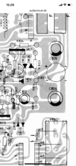
Across the leads of C805 and C806 there are 60 V DC (expected?) - but also close to 500 mV AC (not expected?)
Assuming this is unintended (?) I looked at the function of the close by diode D805. I had to ask Co-pilot how to use my Fluke for this.
Below, note that I do not understand why red vs black behaves “in reverse” compared to what is expected per fluke manual.
First I put RED on + and looked at voltage drop to the three - poles
Pin 1) multimeter switches between about 2 V drop and OL.
Pin 2) OL.
Pin 3) multimeter switches between about 2 V drop and OL.
Next I put BLACK on + and looked at voltage drop to the three - poles
Pin 1) 0.54 V drop
Pin 2) 1.1 V drop
Pin 3) 0.54 V drop
Does this indicate that the diode is bad - and a potential cause for AC “on the line”?
Attachments
Across the leads of C805 and C806 there are 60 V DC (expected?) - but also close to 500 mV AC (not expected?)
Assuming this is unintended (?) I looked at the function of the close by diode D805. I had to ask Co-pilot how to use my Fluke for this.
500mv ripple sounds normal. The caps are low value (470uF) and the supply is 'raw' with no stabilisation or regulation.
D805 is a diode bridge of four diodes.
Below, note that I do not understand why red vs black behaves “in reverse” compared to what is expected per fluke manual.
First thing is to say that checking parts in circuit often gives unreliable results due to interaction with other parts.
On the diode range your (digital) meter will put out a test voltage and the red lead will be the positive. When checking a diode the diode will conduct when the red lead is on the anode and the black on the cathode. Analogue meters often have the polarity reversed on ohm and diode ranges... its just the way they are.
The diode bridge is extremely unlikely to be faulty.
Here is a similar setup as a simulation. 470uF caps with1k across them which at 60 volt rails draw 60 milliamps load current.

This is the ripple on each rail which is over 1 volt peak to peak:

This is the ripple on each rail which is over 1 volt peak to peak:
Ok, thank you - so my 500 mV AC in this position is not unexpected.
A previous post adviced me to look for AC ripple on the 25 V rails.
Could you point me to where on the PCB I find this - and what AC to expect?
Any other suggestions I can pursue?
Remember that the hum is specific to the pre-amp section. And It is not dependent on what input I use. And it disappears when the low-level switch is engaged (completely and at all volume settings).
Last edited:
500mv as measured on a meter sounds about right. The meter will try and give an rms value rather than peak to peak. I got around 600mv rms working it out from the image.

You need to find the points I circled on the diagram. It will be easiest to measure across the caps that are across the rails, these four circled. There should be virtually zero ripple here, we are talking a millivolt or two at most.Could you point me to where on the PCB I find this - and what AC to expect?
I believe I managed to ID these caps (two electrolytic and two ceramic). Hard to read in the numbers on the schematic, but hope you can see if I did it right by the numbers? Does it look like I found the correct ones?
What I measure:
C810: 47.9 V DC, <0.5 mV AC
C811: 48.4 V DC, <0.5 mV AC
C819: 26.4 V DC, <0.5 mV AC
C818: 25.8 V DC, <0.5 mV AC

Next: I poked around to see if I can affect the hum by moving cables, touching components or the PCB etc. I note that if I touch a screwdriver especially to some of the solder points in the “speaker EQ” section, the hum magnifies quite a lot. This to me indicates that I am picking up something from “the outside” - does this make sense?
And still - all hum disappear when activating the “low level” button.

What I measure:
C810: 47.9 V DC, <0.5 mV AC
C811: 48.4 V DC, <0.5 mV AC
C819: 26.4 V DC, <0.5 mV AC
C818: 25.8 V DC, <0.5 mV AC
Next: I poked around to see if I can affect the hum by moving cables, touching components or the PCB etc. I note that if I touch a screwdriver especially to some of the solder points in the “speaker EQ” section, the hum magnifies quite a lot. This to me indicates that I am picking up something from “the outside” - does this make sense?
And still - all hum disappear when activating the “low level” button.
Last edited:
Those ripple values look good.
Touching parts in the signal path will introduce hum as you are injecting stray pickup from the radiated fields (that are all around us) directly into the amp.
You really need to trace this with an oscilloscope so you can see what is happening.
Have you fitted shorting links to the input you are using/testing with? If the input is floating it can pick up noise and hum.
Touching parts in the signal path will introduce hum as you are injecting stray pickup from the radiated fields (that are all around us) directly into the amp.
I can't identify that on the circuit diagram as the switches are not labelled. If it is just an attenuator then it may give the impression of removing the hum simply because it lowers the amplitude of the hum (and the wanted signal) by a large amount.And still - all hum disappear when activating the “low level” button.
You really need to trace this with an oscilloscope so you can see what is happening.
Have you fitted shorting links to the input you are using/testing with? If the input is floating it can pick up noise and hum.
I just tried shorting the input. No effect.
You are probably right, I need someone with a scope to help me out.
I just really hoped that I could find the problem myself 🙂
You are probably right, I need someone with a scope to help me out.
I just really hoped that I could find the problem myself 🙂
I have no idea - I tried to find the correct ones but not sure I found them 😅My glasses have to be betraying me again 🙂 - where are the smoothing caps of 25V rails?
If you can point to the specific ones on the PCB layout image above/in the service manual it would help. Just to verify if I am measuring the right ones.
It is page 6 in this one: SM
If I could do that then I would not be asking about them 🙂If you can point to the specific ones
Fair 🙂
I think I found the wrong ones / I cannot understand why the two 25 V rail ones would be one ceramic and one electrolytic - would it not be “symmetrical”, i.e. the same type and value for 25 and 45 V, respectively?
I think I found the wrong ones / I cannot understand why the two 25 V rail ones would be one ceramic and one electrolytic - would it not be “symmetrical”, i.e. the same type and value for 25 and 45 V, respectively?
The -/+25 and -/+45V rails all come from the upper bridge D805 and 470uF reservoir caps. The output of the regulators need only the small value caps shown.

Thank you - yes I understand that they come from the same original source. However, trying to understand the schematic vs my readings.
Would I not expect same readings across the two red ones and the two green ones, respectively?
Am I correct that
1) the two green ones are located between ground and 25V + and -, respectively?
2) top red one is located between ground and +45V?
3) bottom red one is located between -45V and ??

Would I not expect same readings across the two red ones and the two green ones, respectively?
Am I correct that
1) the two green ones are located between ground and 25V + and -, respectively?
2) top red one is located between ground and +45V?
3) bottom red one is located between -45V and ??
- Home
- Amplifiers
- Solid State
- NAD 3140 ghost capacitor, hum problem & VU meter