so im currently running the amp at around 15ma, which is nothing realy, but it sounds great and the volume levels are, well normal, untill you use the frequency equalisation switch
when you switch it to the 70hz position and it goes realy loud just on the right channel, very odd
so im going to pull this out, strip it down and clean it, see what happens
im also going to realy look closely at the grounding in this area
when you switch it to the 70hz position and it goes realy loud just on the right channel, very odd
so im going to pull this out, strip it down and clean it, see what happens
im also going to realy look closely at the grounding in this area

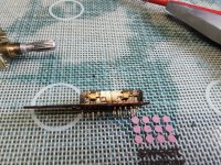
That's really gungy, something like that will surely be the cause of the different levels as you operate the switch.
So back to this as the noise issue was never resolved. All I ever really proved was the noise got worse near Led lights
That is radiated interference then. The amp may just not be very immune to that kind of thing if they are to close.
So the noise used to increase as you increased the bias, which at the moment is quite low, so I need to try and increase it without the lighting influence
Increasing the bias should really only increase ripple on the rails.
Try connecting a 100 watt bulb across the two rails (the + rail to the - rail) and see if that increases the noise. It should pull 100ma or more at a low voltage. Hard to predict exactly how much because the filament resistance will be lower when it runs cooler.
Try connecting a 100 watt bulb across the two rails (the + rail to the - rail) and see if that increases the noise. It should pull 100ma or more at a low voltage. Hard to predict exactly how much because the filament resistance will be lower when it runs cooler.
so here is an oddity
if you measure the voltage between the + speaker terminal of the left channel and the source of each FET, you get +/- reading i.e. +41mv/-41mv
but when you do it with the right channel(the one that buzzes mostly) both channels give an neg reading ,so -34/-34, actually you cant take it up more than about 7mv or it starts to buzz, the other channel doesn't do that
You might find the DC offset affects that reading a little and I think you must have the old emitter resistors still in place to be able to measure that volt drop. The DC offset and the bias current are the two important things.
so this is the bias i was reading back
im just doing it as the method described, but that would have been for a BJT
would you do it another way?
im just doing it as the method described, but that would have been for a BJT
would you do it another way?
Volt drop across the resistors is the way to do the bias but if you have a load attached and a DC offset is present it can slightly alter the overall result. So unless the offset really is zero you are best setting the bias with no load.
Forget what I said earlier, I was forgetting you were measuring from the output point 🙂
Forget what I said earlier, I was forgetting you were measuring from the output point 🙂
No load will normally give the most accurate result irrespective of any offset that may be present.
Recheck your readings with no load.
If you are measuring from the plus speaker terminal then I would think the N channel FET should always show a positive result and the lower a negative result irrespective of any offset voltage with respect to ground. The current is the same in each resistor (they are effectively in series) and so one end of the two will always be positive and the other negative.
If you are measuring from the plus speaker terminal then I would think the N channel FET should always show a positive result and the lower a negative result irrespective of any offset voltage with respect to ground. The current is the same in each resistor (they are effectively in series) and so one end of the two will always be positive and the other negative.
I can't just see a way both can be negative tbh.
If the amp offset is near zero we get this. The upper voltage is positive and the lower negative. We have 100ma flowing in each:

Now we give it a negative offset. The upper is still positive by the same amount and the lower is negative by the same. There is the same voltage across each 0.33 and the bias current is the same:

Now we make the offset positive. The upper is still positive with respect to the terminal and the lower is still negative:

If you place the negative lead of the meter on the junction of the 0.33 ohm resistors and then measure to the end of each then with the bias set to say 100ma you have to see a positive voltage on the top one and negative on the lower one.
They can all be positive or negative as measured from ground but I can't see how they can both be one or the other when measured from the positive speaker terminal.
The only exception to all that might be if there is AC present and the meter is not showing a true reading... and that is checked with the scope of course.
If the amp offset is near zero we get this. The upper voltage is positive and the lower negative. We have 100ma flowing in each:
Now we give it a negative offset. The upper is still positive by the same amount and the lower is negative by the same. There is the same voltage across each 0.33 and the bias current is the same:
Now we make the offset positive. The upper is still positive with respect to the terminal and the lower is still negative:
If you place the negative lead of the meter on the junction of the 0.33 ohm resistors and then measure to the end of each then with the bias set to say 100ma you have to see a positive voltage on the top one and negative on the lower one.
They can all be positive or negative as measured from ground but I can't see how they can both be one or the other when measured from the positive speaker terminal.
The only exception to all that might be if there is AC present and the meter is not showing a true reading... and that is checked with the scope of course.
OK I check with the scope, but they are both negative. I know it doesn't make sense, I agree, but they are both neg
The current flowing in the upper 0.33 ohm enters the node that is the junction of the two resistors. The current then leaves that node and flows into the lower 0.33 ohm.
If both voltages are negative (and it is a true DC reading) then it violates first Kirchhoff's Rule which says that the sum of currents flowing into a circuit node has to be equal to thee sum of the currents leaving that node.
If both voltages are negative (and it is a true DC reading) then it violates first Kirchhoff's Rule which says that the sum of currents flowing into a circuit node has to be equal to thee sum of the currents leaving that node.
Kirchhoff's Rule appears to be safe
this for some reason is ok now, so put it down to user error
so back to the noise issue
with the right load disconnected i can take the bias up to 1.22ma without any noise so 0.27mv/0.22, although the lamp does start to get quite bright at that, and that isnt needed obviously
but with the left disconnected the right channel connected it starts to buzz at about 0.06mv/0.22 = 0.27ma and the lamp starts to get bright, so im not sure whats going on with the current here
centres are both ok at near 0v
- Home
- Amplifiers
- Solid State
- NAD 3140 Conversion to lateral FETS