Not necessarily, the radiated pattern isn't always uniform and you can get a different result simply by rotating the transformer relative to the nearby PCB/wiring to find a null.
First you have to determine the source of the noise though. The transformer is only one possibility and it would be more of a pure deep hum at the fundamental frequency of the mains if it were that.
First you have to determine the source of the noise though. The transformer is only one possibility and it would be more of a pure deep hum at the fundamental frequency of the mains if it were that.
OK I understand what you mean. It's quite weird, the noise changes tones from lower to higher frequencies when you tap the board as well, and not in specific places, so it isn't going to be easy to find
That really looks like a physical issue, the board not grounded properly via a screw perhaps. You will have to poke, prod and bend the board to try and see where it occurs. Also any wiring to to and from the board.It's quite weird, the noise changes tones from lower to higher frequencies when you tap the board as well,
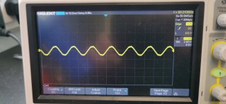
That's showing as 50Hz which is the mains fundamental frequency. You need to look very carefully at both channels output because if you see and measure the same on each, then each should have the same level of audible noise. Any distortion or spikiness in the waveform will make it much more audible.
Use both channels on the scope and display both outputs together and then its easy to compare. Also be aware of any changes that the scope might introduce through ground loops via the leads and the mains.
Use both channels on the scope and display both outputs together and then its easy to compare. Also be aware of any changes that the scope might introduce through ground loops via the leads and the mains.
one thing i have just found
If i touch the base of Q608 with my meter probe the noise dissapears
If i touch the base of Q608 with my meter probe the noise dissapears
That kind of thing can be a symptom of instability at very high frequency. Although you obviously can't hear the instability directly it can cause effects all across the audio band.
You really need to see if you can see it on the scope. Can you see the noise disappear when you touch that point. Use both channels of the scope to investigate.
You really need to see if you can see it on the scope. Can you see the noise disappear when you touch that point. Use both channels of the scope to investigate.
So that all sounds like ultra high frequency oscillation where just a few pF of capacitance from the scope probe changes things.
First just recheck that everything is absolutely correct and both channels 100% match each other for parts value and in terms of what has been removed and what has been linked out and so on.
It might be worth looking around these caps. The circuit actually looks wrong with a 0.1uF cap in parallel with the 220pF.
Another thing to try as a quick check is to increase the gate stoppers to say 1k which will reduce the bandwidth of the output stage. It might give a clue what is happening.
so just to clarify.It isnt the scope probe that stopped the noise, but the multimeter.Putting the probe from the scope on doesnt stop the noise.So that all sounds like ultra high frequency oscillation where just a few pF of capacitance from the scope probe changes things.
First just recheck that everything is absolutely correct and both channels 100% match each other for parts value and in terms of what has been removed and what has been linked out and so on.
It might be worth looking around these caps. The circuit actually looks wrong with a 0.1uF cap in parallel with the 220pF.
Another thing to try as a quick check is to increase the gate stoppers to say 1k which will reduce the bandwidth of the output stage. It might give a clue what is happening.
View attachment 1192009
with the scope on the speaker terminal and the MM probe tip on the base of Q608 it looks like this and the noise goes totaly(audible)
The noise also goes if you place the MM tip on either leg of C610 and C616 so im going to concentrate my efforts around that area for now.
Attachments
![IMG_20230712_074005[1].jpg](/community/data/attachments/1099/1099921-622a22a9421697759131db3bf139a961.jpg?hash=YioiqUIWl3)
Perhaps more stray capacitance with the DMM.so just to clarify.It isnt the scope probe that stopped the noise, but the multimeter.
The other NAD we did was a 3020 (I think) and this one is a little different in minor details. The gate stoppers are still worth trying but I also notice the 3020 has a 100pF cap across the main feedback resistor and the 3140 does not. These are R623 and R624, the 680 ohm 1 watt. It might be worth seeing what a very small value cap does across those resistors, lets say a 47 or 68pf as a test.
so i have found something that might make a difference
on the other good channel R635 33ohm is to ground
on the bad channel R636 isnt in place, but i also cant find it on the diagram, unless you guys can see it
but im going to put it in place and see if it makes a difference
on the other good channel R635 33ohm is to ground
on the bad channel R636 isnt in place, but i also cant find it on the diagram, unless you guys can see it
but im going to put it in place and see if it makes a difference
ill give it a try, but i always ask the same question, why is it ok on the other channelPerhaps more stray capacitance with the DMM.
The other NAD we did was a 3020 (I think) and this one is a little different in minor details. The gate stoppers are still worth trying but I also notice the 3020 has a 100pF cap across the main feedback resistor and the 3140 does not. These are R623 and R624, the 680 ohm 1 watt. It might be worth seeing what a very small value cap does across those resistors, lets say a 47 or 68pf as a test.
View attachment 1192026
so a 47pf cap makes it worsePerhaps more stray capacitance with the DMM.
The other NAD we did was a 3020 (I think) and this one is a little different in minor details. The gate stoppers are still worth trying but I also notice the 3020 has a 100pF cap across the main feedback resistor and the 3140 does not. These are R623 and R624, the 680 ohm 1 watt. It might be worth seeing what a very small value cap does across those resistors, lets say a 47 or 68pf as a test.
View attachment 1192026
That's an interesting one, that resistor is shown as in series with a 0.1uF to ground which implies some kind of decoupling although 33 ohms seems crazy high.on the other good channel R635 33ohm is to ground
I've no simple answer, you need to look logically and try various things. Its all part of the learning experience 🙂
Decoupling around the output stage is important. Try those 0.1uF's as they are shown on the diagram perhaps directly across the rails. Bizarrely the positive rail is shown decoupled via a 22 ohm. If the Lateral FET have longish wires to the Drains (which is the supply) then decoupling those points to ground could be worthwhile.
Most likely because the oscillating channel is on a knife edge and even the slightest differences in board layouts between the channels and length of ground runs makes a big difference. This is all typical behaviour of how extreme high frequency circuitry behaves. Things like a few cm of PCB print that seem 'a short circuit' are anything but when looked at in the 10's and 100's of Mhz.ill give it a try, but i always ask the same question, why is it ok on the other channel
- Home
- Amplifiers
- Solid State
- NAD 3140 Conversion to lateral FETS