having a bit of trouble with this one.Im getting confused by the voltages im getting.Ive not tested all of it yet but i am working methodicaly backwards from the speaker terminals
it is simlar to the series 20, but there are differences.
heres what i have so far
all voltages are with the solder shorts in place
both channels are affected in the same way.
im getting high voltages from the speaker terminals, up to 6v so the centre is way out, and so is alot of the voltages elswhere
i have taken out and tested the main output transistors also Q609 and 610, these are all ok.
many thanks for any thoughts you may have.
Attachments
Last edited:
Your high voltages (according to your measurements ) seem to start around -Q606 and Q608 , I would check them out and the surrounding components.
having a bit of trouble with this one.Im getting confused by the voltages im getting.Ive not tested all of it yet but i am working methodicaly backwards from the speaker terminals
it is simlar to the series 20, but there are differences.
heres what i have so far
all voltages are with the solder shorts in place
both channels are affected in the same way.
im getting high voltages from the speaker terminals, up to 6v so the centre is way out, and so is alot of the voltages elswhere
i have taken out and tested the main output transistors also Q609 and 610, these are all ok.
many thanks for any thoughts you may have.
so no further forward realy, if anything im even more confused
i have removed and tested Q606 and 608 and both tested ok
clip switch has no effect either way so its not something to do with that part.
i have a simlar issue with the other channel although the voltages are not as high,around 2.2v, but still high
so although this circuit has an issue, there must be a more common generic issue beteen both further back maybe??
ill keep plodding on, but if you have any ideas it would be appreciated 🙂
Attachments
Hi I once had a nad 302 with the same problem has you it
Had about 3.6v-4v on both outputs. The fault was in the power supply your amp and the 302 are similar in many ways the fault was c907 47mfd 50v being s/c
Good luck 👍. Jim
Had about 3.6v-4v on both outputs. The fault was in the power supply your amp and the 302 are similar in many ways the fault was c907 47mfd 50v being s/c
Good luck 👍. Jim
What are the (+ or -) voltages on each side of R650 ?
I assume you've check all the PS voltages ?
I assume you've check all the PS voltages ?
nope tried them, they are ok, as are all the others around it.
this one is pretty stuffing me at present.
the thing that stands out to me is the raised voltages generaly
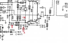
where it says +33v it is actualy +36v
where it says -24v it is actualy -26v
ive checked right back to the rectifier and thats giving out the correct voltages(+39v and -39v)
ive checked Q901 to 904 all ok
at this rate ill end up checking the whole thing from the start.😱
this one is pretty stuffing me at present.
the thing that stands out to me is the raised voltages generaly
where it says +33v it is actualy +36v
where it says -24v it is actualy -26v
ive checked right back to the rectifier and thats giving out the correct voltages(+39v and -39v)
ive checked Q901 to 904 all ok
at this rate ill end up checking the whole thing from the start.😱
What are the (+ or -) voltages on each side of R650 ? I assume you've check all the PS voltages ?
across R605 -26v/-4.5v
so they are not right,not sure why i didnt check thos ones-my heads a bit done in now 🙁
Hi I once had a nad 302 with the same problem has you it
Had about 3.6v-4v on both outputs. The fault was in the power supply your amp and the 302 are similar in many ways the fault was c907 47mfd 50v being s/c
Good luck 👍. Jim
i replaced a couple of electrolitic caps this morning that were grounded and i hadnt yet checked and this has made a massive difference, they were faulty so now i am suspecting there could be a few more.
my voltages are down to 29mv (R) and 130mv (L), thats as low as i can get them with the pots at present.
across R605 -26v/-4.5v
so they are not right,not sure why i didnt check thos ones-my heads a bit done in now 🙁
these are now the correct voltages
these are now the correct voltages
Correct as in? these are what you measure or the voltages are now where they are supposed to be?
R650 and R648 should have identical voltages across each, no matter what other fault you may or may not have.
For example, output at zero volts DC means you have about -1.2 volts on the base of Q614 (which is drawn incorrectly as an NPN in the diagram I have).
If the supply is -26v then you have (26-1.2)/2 which means you have 12.4 volts across each resistor.
Whatever voltage you have on the base of Q614 divided by 2 will give you the voltage you should see across each of those resistors.
The higher supply voltages you measure are no problem and are just down to variations in mains supply voltage and transformer tolerance.
i was just working on this bit.
ive been doing as you said and working methodicaly
voltages are identical down stream of R648 and R650 both -13V,which is fine, but not identical on the upstream side
Q614
B -0.967V as is the other side of R648
C -33V
E -0.513V
R650 upstream of C630 is 26v so im just trying to locate caps C642 and C630, but they are proving illusive, but i will find them
i have found alot of knackered caps in this amp, mainly the ones to ground and the power ones around the power supplies, they were almost half the original values and the ones to ground were shot,C622 i replaced this morning has made a significant improvement as this was totaly dead,but still not correct yet.
I also replaced R640 and its counter part as they were both burned,although in value.
C630 is -33v which is correct but 26v upstream-this according to the diagram should be around 24v so could this cap be faulty, its a poly cap
Last edited:
I'm not really following what you are saying here. What fault are you chasing?
R650 has -26 volts on one end. It goes to the negative supply marked as -24v. So -26v is fine.
Q614 base is at -0.967 volt. That sounds OK.
One end of R648 has to be at -0.967 volt because it connects to the base of Q614.
Then you say:
So that suggests either a short across R648 or R648 is the wrong value (much to low).
That also implies R650 is now dropping the full -26 volts and so will be getting to hot.
R650 has -26 volts on one end. It goes to the negative supply marked as -24v. So -26v is fine.
Q614 base is at -0.967 volt. That sounds OK.
One end of R648 has to be at -0.967 volt because it connects to the base of Q614.
Then you say:
B -0.967V as is the other side of R648
So that suggests either a short across R648 or R648 is the wrong value (much to low).
That also implies R650 is now dropping the full -26 volts and so will be getting to hot.
sorry i have just double checked this and all is ok, as i thought that 26v was too high so thats ok then
what im chasing is the centre voltages, this is what i have been doing
so the right channel is now -30mv and the left channel is -100mv, this is as low as they will go with the pot adjustment, they were originaly 5v before i changed caps C622 and C621
they are 2k pots and i have tested them and they have full range adjustment, so i guess now i have to go back over it as everything has now changed from my original checks
Just so we are sure, these are the three key voltages. What do you measure for each.
A= -26v
B= -13v
C= -1v
OK 🙂
The NAD circuit has no real pretensions to DC stability because of the circuit configuration, it just works 'acceptably' well for DC stability and fitted with the standards of the day back when it was designed.
So to get the midpoint correct you need to first determine which end of the adjustable range the preset is turned to.
Is it set at zero ohms or is it set at 20k?
If it set to zero ohms now then you need to reduce the value of R618. Try a 470 ohm.
If it is set to 20k then you need to increase R618. Try a 2k2.
If you still can not get the correct point doing that then you may need to alter R616
im glad i was thinking of the same thing as what you are suggesting so this is what i am now doing
both pots are 0 ohms so im going to try changing the resistors
both pots are 0 ohms so im going to try changing the resistors
- Home
- Amplifiers
- Solid State
- NAD 3020b