oh of course
ive worked hard on this as there were alot of parts faulty and could have sent me round in circles, but i stuck to what you said and didnt give up.
i let you know how it goes
ive worked hard on this as there were alot of parts faulty and could have sent me round in circles, but i stuck to what you said and didnt give up.
i let you know how it goes
470 made it worse, so ive thrown in a 2k trimmer and got it down to 2mv-tolerence +/- 10mv
could i leave this in or would you use a fixed one
could i leave this in or would you use a fixed one
all good, off set 0mv both channels😀OK, good luck
when i first turned it on there was a bit of a buz, just very breifly.
there is no cap fitted across the mains switch on this one, but i have seen it on others
worth fitting one?
amp seems ok, been using it for a while and the offset seems unchanged
its this initial buzz thats bothering me.remember metal micky from the 80's, sounds a bit like a noise he would make, just briefly, about 3 seconds after turning on, then its gone, but it does it everytime.capacitor? maybe
its this initial buzz thats bothering me.remember metal micky from the 80's, sounds a bit like a noise he would make, just briefly, about 3 seconds after turning on, then its gone, but it does it everytime.capacitor? maybe
470 made it worse, so ive thrown in a 2k trimmer and got it down to 2mv-tolerence +/- 10mv
could i leave this in or would you use a fixed one
Personally I would always go 'fixed'. Measure the trimmer resistance and fit the nearest fixed value.
there is no cap fitted across the mains switch on this one, but i have seen it on others
worth fitting one?
Probably not 😉 Its made it this far without. Its easy to cause more problems as well.
amp seems ok, been using it for a while and the offset seems unchanged
its this initial buzz thats bothering me.remember metal micky from the 80's, sounds a bit like a noise he would make, just briefly, about 3 seconds after turning on, then its gone, but it does it everytime.capacitor? maybe
Does it still do it if you pull the Pre-Out / Main-In jumpers and then turn it on ?
Do as Goldie suggests which will split the amp in two and show if it is a 'problem' with the power amp stage or whether the power amp is just amplifying whatever the preamp is sending it.
It may just be a 'characteristic' rather than a problem. Our expectations were not as high back in the day and you might just be chasing limitations of the design.
^ Yup. I would change all three tbh and also check the 150k's (R547 and R548) are OK.
Didn't you have one of these faults a few weeks back and we looked at the sim of the muting circuit. Wasn't the auxiliary contact on the mains switch a suspect back then?
Didn't you have one of these faults a few weeks back and we looked at the sim of the muting circuit. Wasn't the auxiliary contact on the mains switch a suspect back then?
no that was another guy i think, and he was looking for a new switch
i had a centre issue with the soft clip on a 3130, maybe it was that you were thinking of.
i will change the caps, as i have all of them and the resistorsin case they are faulty
i had a centre issue with the soft clip on a 3130, maybe it was that you were thinking of.
i will change the caps, as i have all of them and the resistorsin case they are faulty
I thought it had cropped up before.
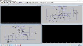
The mains switch could be a suspect with that auxiliary contact. Here is the sim for the NAD. The FET's mute the audio when the gate voltage is negative. They are wired as simple series switches.
These were the two sims I did earlier.
Breadboards...
The mains switch could be a suspect with that auxiliary contact. Here is the sim for the NAD. The FET's mute the audio when the gate voltage is negative. They are wired as simple series switches.
These were the two sims I did earlier.
Breadboards...
Attachments

great thanks for that.i have loads of components, the only thing i havent realy done yet in basics are FETS, so i need to learn about those🙂I thought it had cropped up before.
The mains switch could be a suspect with that auxiliary contact. Here is the sim for the NAD. The FET's mute the audio when the gate voltage is negative. They are wired as simple series switches.
These were the two sims I did earlier.
Breadboards...
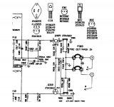
R549 in the real amp is just to prevent arcing and pitting of the switch contact as it 'shorts' out cap C3. In the sim it is left open.
When the amp is off the switch is closed. When the amp is on the switch opens.
FET's are very different to normal transistors.
A couple of quick bits of info.
1/ Small signal FET's like these are truly symmetrical. That means that Drain and Source actually have no real meaning and can be interchanged and swapped around. That only applies to these small J-FET's (junction FET) types.
2/ The gate has near infinite input impedance. This mean if you test a FET out of circuit between D and S you may or may not find it has continuity. The reason is the gate can pick up stray charge. Touch the gate with a finger and it might turn it on or off depending how the gate channel sees any charge. That charge will remain for hours.
Look at the NAD circuit (the real one, not the sim) and D507 that goes to the FET gates. The diodes leakage current is more than enough to be able to pull the FET gates negative. The diode is reverse biased when muted (non conducting) but is still conducts enough to work and to be able to pull the FET gates negative.
3/ When the gate to source voltage difference is close to zero volts the FET is on (and so has a low resistance between D and S) To turn the FET off the gate is pulled negative by a few volts. How many volts is needed is called the 'pinch off' voltage and varies a lot between different FET's.
4/ Power FET's are very different and these have a 'parasitic' diode that is formed by the production process appearing between D and S. This makes them non symmetrical and they must always be used with correct polarity between D and S. Similar to C and E and NPN and PNP transistors.
You can get a good feel for the FET with your breadboard and a simple circuit with a resistor and LED.
JFETS are reasonably immune to static, certainly with the normal humidity conditions in the UK. Think and be careful rather than go to extreme measures I would say. So don't run around on a nylon carpet 😀 If you are sat at a bench or table near a wall then just placing your hand on the wall for a second will remove any charge from you.
The FET's in that diagram are just connected as series switches. When the gate is pulled negative the FET is off and has a very high resistance (100's of meg ohms). So no audio gets through.
When the gate drive voltage reaches around -3 volts (guessing... typical value) and higher (so closer to zero) the FET turns on and has a low resistance of tens of ohms. So it passes audio.
If the drive voltage exceeds around + 200 to 300 millivolts the gate to source/drain channels conduct a bit like the diode volt drop across a b-e junction. In the NAD the 10 meg resistors ensure that current flow is microscopic. Remember the FET is voltage driver and so those 10meg resistors could just as easily be 100 or 1000 meg and it would still work.
very conflicting, drawing says 63v and spec 100vTry changing C531, and eventually C533, ideally with 100V rated equivalents.
Use the simulation to see what sort of voltages you might see.
C532 can see almost 35 volts across it.
C533 sees almost 65 volts across it.
C531 sees (in my sim) just over 70 volts.
I'm probably running the sim at the top end of the expected voltages but I would say 63v rating is to low for C531 and C533. A manufacturer may fit 63v parts there to save costs and on the basis they will last a few years under normal use. Not good practice though.
- Home
- Amplifiers
- Solid State
- NAD 3020b