So another slightly odd issue.
You must use a bulb on this. As you turn the preset to a lower value (toward zero ohms) the voltage across Q609 should rise. 5K is not really going to give much resolution and this could be an all or nothing thing which could cause damage.
Look at the voltage across Q609 to begin with.
If you have turned the pots to zero ohms and nothing happened bias wise then you have a fault around the output stage.
Im just working though it at the moment, and when im working on any amp till its finished im always on the bulb supplySo another slightly odd issue.
You must use a bulb on this. As you turn the preset to a lower value (toward zero ohms) the voltage across Q609 should rise. 5K is not really going to give much resolution and this could be an all or nothing thing which could cause damage.
Look at the voltage across Q609 to begin with.
If you have turned the pots to zero ohms and nothing happened bias wise then you have a fault around the output stage.
Q610 has only 400mv on the base so im working my way back at the moment.should be about 800mv
i didMaybe a silly Q., but did you remove the solder shorts on R653 / 654 ?
Q610 has only 400mv on the base so im working my way back at the moment.should be about 800mv
Measured from where though? The base voltage always has to be referenced to the emitter to determine what is going on. 400mv across B/E is not enough to turn it on, but having said that with it not on you should have excess idle current. So you have a fairly basic kind of fault here I think.
im only following what the book saysMeasured from where though? The base voltage always has to be referenced to the emitter to determine what is going on. 400mv across B/E is not enough to turn it on, but having said that with it not on you should have excess idle current. So you have a fairly basic kind of fault here I think.
alot of people say the amps are pretty much the same, but they are not exactly and neither are the instructions, nor are they that clear, well 3020b isnt.
i am following 3020b but i dont think that is the issue
the voltages shown on the diagram EG where it says -Q610 base it should be -0.8v(800mv), its actualy -0.4v(400mv) and all of the voltages are generaly down on what they spec untill you get to the positive rail where it is +36v not +33v
Q608 emitter for example is +1.02v not +1.4v
Q606 base for example is +1.6v not +2.0v
etc etc
im just going to start having another look now.🙂
ive given up for today, replaced a couple of transistors, now ive got 31v on all the speaker outlets,so im pulling out till tomorrow.😱
If you have a high DC offset then begin with Q609 linked out.
I wouldn't worry over exact voltages on those transistors, what matters is getting the offset close to zero. Once that is done the other voltages will fall into place... they have to because you can work back from the output and write the expected voltages on to the diagram and they will come out close to what NAD have written.
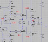
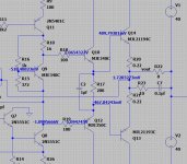
This is from a different amp but it is similar configuration. First image are what I would have 'expected' if asked. Second is what the sim says.
The voltages are all logical and and form a logical progression. So don't get hung up on looking to achieve certain voltages at certain points in the circuit because that will never work.
Get the midpoint correct first (short out Q609) and then take it from there.
I wouldn't worry over exact voltages on those transistors, what matters is getting the offset close to zero. Once that is done the other voltages will fall into place... they have to because you can work back from the output and write the expected voltages on to the diagram and they will come out close to what NAD have written.
This is from a different amp but it is similar configuration. First image are what I would have 'expected' if asked. Second is what the sim says.
The voltages are all logical and and form a logical progression. So don't get hung up on looking to achieve certain voltages at certain points in the circuit because that will never work.
Get the midpoint correct first (short out Q609) and then take it from there.
Attachments
ok will do tomorrow.
i dont realy get hung up, if they look reasonable i accept them and all was looking good, i put the 2 fixed resistors back (RX1 AND 2) and got 7mv across each of the 2 resistors R653 AND R654, which according to the spec is fine but before i changed them ,and i had the variables in, when i turned down too much the lamp started to glow, which is why i put the fixed ones back.
after changing a couple of resistors that had failed Q602 and Q604 i ended up with 30+ odd volts on the back, so maybe ive done something wrong somewhere(although i did check the orientation and they were right) so who knows, its like the other amp, it shows a certain pattern on the amp and diagram, but im affraid i dont trust them anymore.so for now i am reserving judgement before i execute myself do putting them in wrong😉
If you have a high DC offset then begin with Q609 linked out.
I wouldn't worry over exact voltages on those transistors, what matters is getting the offset close to zero. Once that is done the other voltages will fall into place... they have to because you can work back from the output and write the expected voltages on to the diagram and they will come out close to what NAD have written.
This is from a different amp but it is similar configuration. First image are what I would have 'expected' if asked. Second is what the sim says.
The voltages are all logical and and form a logical progression. So don't get hung up on looking to achieve certain voltages at certain points in the circuit because that will never work.
Get the midpoint correct first (short out Q609) and then take it from there.
so update on last night, user error im affraid i put in PNP instead of NPN Q602/Q603(I had a bad day yesterday and im putting it down to that 😉) i looked at your sim and something didnt look right, and it was just that(the npn/pnp bit) so thats what i changed
so now all good from the point is centre 50mv approx on each so i have to sort those out
idle is 22mv(R) -64mv(L)-so i need to sort these out, but i recon we are nearly there as the voltages around the circuit are almost spot on now at all reference points
Last edited:
Forgive me poundy but how did you test the capacitors?
I ask you this because I have repaired and restored several 3020 and 302 and for some reason unknown (to me) some capacitors can keep their capacity but have an incredible ESR, hence my question.
I ask you this because I have repaired and restored several 3020 and 302 and for some reason unknown (to me) some capacitors can keep their capacity but have an incredible ESR, hence my question.
If you have a high DC offset then begin with Q609 linked out.
I wouldn't worry over exact voltages on those transistors, what matters is getting the offset close to zero. Once that is done the other voltages will fall into place... they have to because you can work back from the output and write the expected voltages on to the diagram and they will come out close to what NAD have written.
This is from a different amp but it is similar configuration. First image are what I would have 'expected' if asked. Second is what the sim says.
The voltages are all logical and and form a logical progression. So don't get hung up on looking to achieve certain voltages at certain points in the circuit because that will never work.
Get the midpoint correct first (short out Q609) and then take it from there.
so im a bit stuck here.
i have followed the instructions for the 3020b idle but it is a bit confusing instructions 1-5 are missing and i cant find a version anywhere that includes them(i have attached both here)-
question item no 9-3020b
would you take reading across the trimmer or R653/654
Reading across the trimmer is -654mv on both -adjustment of trimmers makes no difference
reading across R653/R654 0v-adjustment of trimmers makes no fifference untill you turn down too far and the lamp starts to come on.
so would you try using the 3020 method instead? the amps are very simlar, but not exactly the same(see section comparatives)
with regards to the centre voltages the trimmers now dont take it anywhere near the value of 0v, they are around 50mv
so i am thinking i need to change the value/s R618/R616 to allow correct adjustment?
Attachments
so update on previous thread
got round the idle issue, they said use a 2-5k pot but i thought this was too high so i used a 1k pot
I didnt understand why you would use a 5k pot to adjust a resistor range of 480ohms, anyway ive now replaced it with a fixed resistor of simlar value and the idle on that channel is 30mv, which is what they say it should be, i cant do any more than that.
im going to try it on the other channel, then deal with the centre voltage issue
it never rains!!!!
You are stressing over these 🙂 Forget about what the voltages are on or across the trimmer, all that matters is that the offset is close to zero and that the voltage across the 1 ohm tests resistor R653/4 is between the limits NAD say. I would aim for the lower end of the range for reliability.
So are we sorted now?
So are we sorted now?
so i found the issue with the centre voltages
the trimmer pots i used, which were fine when i put them in had a prolem, big flat spots on both, so i took them out and the varnish i used to stop them from moving had seeped inside them both and run onto the tracks!
so there you go, simple as that, but i wouldnt have thought to look at that TBH ,not to start with
so all good now, idle and centre are both set, all good.
my only concern is its getting quite hot, and i ve not run it realy high yet.
Heat is proportional to the idle current. The 1 ohm test resistor means the millivolt reading across it translates directly into milliamps.
For example 30mv with -/+30 volt rails is a dissipation of 1.8 watt per channel while 60mv is 3.6 watt dissipation. Two channels so you have to add both channel results together. It doesn't sound a lot but it can be surprising how much it heats up an amp.
For example 30mv with -/+30 volt rails is a dissipation of 1.8 watt per channel while 60mv is 3.6 watt dissipation. Two channels so you have to add both channel results together. It doesn't sound a lot but it can be surprising how much it heats up an amp.
well just to make sure ive removed the solder shorts and just re checked the idle, and both are 28mv, so they are within the +/- 10mv they specify
i do wish i could know what 1-4 would have said.
i have had to backward engineer a guess it said somehting like
remove the solder shorts across R653 and R654 and check voltage across R653 and R654
voltage should be 30mv +/- 10mv??
ill keep using it for a while and see how it goes
i do wish i could know what 1-4 would have said.
i have had to backward engineer a guess it said somehting like
remove the solder shorts across R653 and R654 and check voltage across R653 and R654
voltage should be 30mv +/- 10mv??
ill keep using it for a while and see how it goes
Heat is proportional to the idle current. The 1 ohm test resistor means the millivolt reading across it translates directly into milliamps.
For example 30mv with -/+30 volt rails is a dissipation of 1.8 watt per channel while 60mv is 3.6 watt dissipation. Two channels so you have to add both channel results together. It doesn't sound a lot but it can be surprising how much it heats up an amp.
a quick question
does a DMM plugged into the speaker terminals, have any impact if you monitor the voltages while it is in use playing music?
- Home
- Amplifiers
- Solid State
- NAD 3020b