And.... I still haven't given up on adding an MC/MM circuit to the series 20.
the A and B versions had it, but the A is very very simlar to the late series 20 so I recon it's possible. So to make the ultimate version. FET based, all gold, soft clip LED and MC phono capability
the A and B versions had it, but the A is very very simlar to the late series 20 so I recon it's possible. So to make the ultimate version. FET based, all gold, soft clip LED and MC phono capability
That would be an ultimate version. You could maybe turn up a kit for a suitable phono preamp and build it into the amp if there was enough space.
Do you mean this particular 3020 or in general? It does suggest that a lot of praise heaped on them over some 45 years, is too generous. I've never been a fan but I've fixed enough of them to know what they sound like and that it's unwise to criticise someone's else's choice of gear without invitation." Sounds miles better than the original IMO"
Do you mean this particular 3020 or in general? It does suggest that a lot of praise heaped on them over some 45 years, is too generous. I've never been a fan but I've fixed enough of them to know what they sound like and that it's unwise to criticise someone's else's choice of gear without invitation.
Just my opinion Ian, and i have also fixed quite a few of these now to know what the originals sound like, and compared to the originals, i think with the FETS it sounds cleaner, and that is using exactly the same set up
Initially with KEF concords 1V's, and once im confident its all good, through my fyne audio 303i's
The originals have a very 'soft' sound, very good, but i always prefer sounds that are crisper and brighter, which is why i personally think it sounds better for that reason, others might listen and not like it, its just personal preference.

That's been quite interesting to follow. Mosfets are something I hadn't considered for dealing with the NAD's troublesome output stage, mostly for reasons of tradition, original design spec. and likely objections from owners. I'm impressed that it turns out to sound as good as you say and many thanks too, to Mooly for his guidance and encouragement. Nice going, folks
I wouldn't know half as much as I do without mooly's assistance, so thanks again. This was I have to say, very challenging,in more ways than one, not withstanding the mounting and connection alone of the FETS. The poor old PCB suffered a bit in the process so I have a bit of tidying up to do
Thanks for the kind words 🙂 I know we jumped through a few hoops with that faulty channel to get it all where it is now.
I was doodling with the circuit.
The Lateral's are super easy to drive and that allows the drivers themselves to be ditched in the NAD (I think it would work well). The VAS current is high enough to drive the capacitive loading they present.

We could ditch the vbe multiplier and use a preset or fixed resistor.

Going further maybe a different VAS transistor and ditch the quasi PNP/NPN combo.

Hmmm... its all about learning and trying different set ups. How about 😱 a HEXFET version. These have compatible pinouts to the original devices and are much cheaper.
I was doodling with the circuit.
The Lateral's are super easy to drive and that allows the drivers themselves to be ditched in the NAD (I think it would work well). The VAS current is high enough to drive the capacitive loading they present.
We could ditch the vbe multiplier and use a preset or fixed resistor.
Going further maybe a different VAS transistor and ditch the quasi PNP/NPN combo.
This was I have to say, very challenging,in more ways than one, not withstanding the mounting and connection alone of the FETS. The poor old PCB suffered a bit in the process so I have a bit of tidying up to do
Hmmm... its all about learning and trying different set ups. How about 😱 a HEXFET version. These have compatible pinouts to the original devices and are much cheaper.
Thought you might find this interesting
Comparison temps half volume-3020 FET AMP
P (L) -60c
N (L)-61c
P (R)-61c
N (R)-61c
Left PNP driver 59c
Left NPN driver 59c
Right PNP driver 61c
Right NPN driver 61c
Heatsink temp at base 59c
Heatsink temp at top of fins 43c
Room Ambient 23.4c
Comparison temps half volume-3020 BJT AMP
P (L) -53c
N (L)-57c
P (R)-56c
N (R)-54c
Heatsink temp at base 58c
Heatsink temp at top of fins 40c
Room Ambient 23.4c
Left PNP driver 43c
Left NPN driver 47c
Right PNP driver 49c
Right NPN driver 47c
Thing that is more obvious to me is how more even and stable the temps are for the FETS
Well it wouldnt be difficult to doThanks for the kind words 🙂 I know we jumped through a few hoops with that faulty channel to get it all where it is now.
I was doodling with the circuit.
The Lateral's are super easy to drive and that allows the drivers themselves to be ditched in the NAD (I think it would work well). The VAS current is high enough to drive the capacitive loading they present.
View attachment 1085114
We could ditch the vbe multiplier and use a preset or fixed resistor.
View attachment 1085116
Going further maybe a different VAS transistor and ditch the quasi PNP/NPN combo.
View attachment 1085117
Hmmm... its all about learning and trying different set ups. How about 😱 a HEXFET version. These have compatible pinouts to the original devices and are much cheaper.
thing i notice on your sim is the preset value
with the drivers in place this value is currently 469mv on each channel, i notice yours is 1.7k
same as the BJT'SHi Poundy, what's the output power with latfets/bjts?
did you boost the psu or used some other magical trick 🙄?same as the BJT'S
nope nothing like that
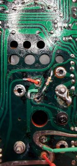
it was difficult to site them though as the GATE/BASE stays where it is, but the collector/drain and emmiter/scource have to be swapped over underneath, so all legs need to be sleeved through the board so they can be crossed over the print underneath
this was the first early one and is basicaly what you have to do as the resistor has to be attached to the leg of the gate
im still learning all this stuff but its great fun,if a bit risky playing around with a perfectly good 3020 worth upwards of £200
Attachments
I meant, how did you manage to get the same power output with latfets? Did you perform any measurements ?
Thought you might find this interesting
Comparison temps half volume-3020 FET AMP....................
Very close indeed. When idling the latfet and bjt should be similar for any given bias current.
Thing that is more obvious to me is how more even and stable the temps are for the FETS
That tends to be the case with laterals. Around 100ma bias current is considered optimal but the heatsink size is a bit to small to run them at that,,, and the same arguments can apply to the bjt's as well.
Hi Poundy, what's the output power with latfets/bjts?
same as the BJT'S
That's one for Mooly
I think what Jacques is getting at is that the FET's don't behave quite like ordinary transistors. Whereas a transistor has current gain, a FET has the different property of 'Transconductance' which is how much the Drain current varies in relation to the Gate to Source voltage.
This means the ordinary transistor can be made to conduct harder by supplying it with more base current. The FET gate works on voltage, not current and so to get it conduct harder we increase the gate voltage.
What all that means is that depending on the load current required (if we want more current), then the gate voltage needs to increase. The effect of that is that when loaded into say 8 ohms is that the driver voltage to the gates needs to go higher.
This shows the output voltage and the FET gate voltage. The load is 8 ohms. See how the drive voltage needs to be higher. This means that the amp will deliver less maximum voltage swing into a load than with ordinary transistors (but you won't notice that listening to it).
So our simulation using 30 volt rails we can deliver around 15.5 volts rms into 8 ohm which is 30 watts rms.
This is the standard version at clipping. This delivers around 19 volts rms into 8 ohm which is 45 watts rms.
Note... reality and simulation may be slightly different. Also note how the base voltage of the ordinary transistor doesn't rise like the FET does. The ordinary transistor needs more base current, the FET needs more gate voltage to conduct harder.
- Home
- Amplifiers
- Solid State
- NAD 3020 Series 20 mk-3 MOSFET Output Conversion