what are the very short drop outs at the peaks on the FET versionHave a look at these and look at the scales and units. The first is the gate current to the upper FET at full output, the second the current into the base of the upper output transistor in the ordinary version.
View attachment 1085191
View attachment 1085192
Good question, and they look terrible don't they?
The NAD is a Class AB amp and that means the output stage has to cross a region of non linearity as the signal crosses the zero point (going from + output to - output). The driver voltage has to 'jump' that region and so it becomes very non linear.
If we reduce the bias to a low value it gets worse.

What you see is the current suddenly changing as it charges/discharges the gate capacitance to move the output stage as best it can across this non linear zone. The output voltage will still look perfect though 🙂 and that is all thanks to the feedback loop.
If we increase the bias current to cover the needed load current then the output stage is biased more toward Class A and does not have this zone to cross (provided the bias is sufficient for the load current).
This is with a higher bias.

This non linearity in the crossover region is inescapable with a low bias Class AB amp, they all do it.
This is the ordinary transistor version and the base current into one of the output transistors. Anything but linear, but the output voltage is fine 😉

The NAD is a Class AB amp and that means the output stage has to cross a region of non linearity as the signal crosses the zero point (going from + output to - output). The driver voltage has to 'jump' that region and so it becomes very non linear.
If we reduce the bias to a low value it gets worse.
What you see is the current suddenly changing as it charges/discharges the gate capacitance to move the output stage as best it can across this non linear zone. The output voltage will still look perfect though 🙂 and that is all thanks to the feedback loop.
If we increase the bias current to cover the needed load current then the output stage is biased more toward Class A and does not have this zone to cross (provided the bias is sufficient for the load current).
This is with a higher bias.
This non linearity in the crossover region is inescapable with a low bias Class AB amp, they all do it.
This is the ordinary transistor version and the base current into one of the output transistors. Anything but linear, but the output voltage is fine 😉
to increase the actual; output value though from say 30 w p/c rms to say 40w you have to increase the rail voltage right? or you wont get enough gain?
The gain is always the same and determined by the feedback factor. So an amp with a gain of 10 will always give 10 volts out for 1 volt in provided the rails allow that. So running on rails of 20 volts or 40 volts or 80 volts, all give the same output voltage for 1 volt input. If you apply 2.5 volts to the input (so 25 volts output) then you need rails of at least 25 volts to allow that.
The gain is always the same when run within its performance envelope i.e. not driven into clipping.
Some amps run the front end and drivers of the power amp on higher voltage rails than the outputs. That is particularly useful for FET's as it lets the drive voltage go that bit higher.
In practice you would find it difficult to tell the difference between two amps where one has just half the power of the other. It is not that noticeable. The voltage gains can be identical, it is just that the lower power one clips earlier.
This amp already has separate rails for the output stage. Trouble is the driver isn’t higher by enough to fully drive mosfets. With a little power supply work you may be able to find a way to increase the driver voltage by the 4 or so extra volts needed. Might not be that hard to add another low current regulator. Certainly something to consider if building one like this from scratch. But getting the full output power like Mooly says just isn’t a big deal - it’s not like wasting 200 watts in heat like a bigger amp would.
There are just so many versions of this thing 😀 Interestingly the negative regulated rail looks to be set lower than the positive one and also neither is higher than the output stage feed.
It is what it is 🙂

It is what it is 🙂
Well it's driving this one just fine, no problemThis amp already has separate rails for the output stage. Trouble is the driver isn’t higher by enough to fully drive mosfets. With a little power supply work you may be able to find a way to increase the driver voltage by the 4 or so extra volts needed. Might not be that hard to add another low current regulator. Certainly something to consider if building one like this from scratch. But getting the full output power like Mooly says just isn’t a big deal - it’s not like wasting 200 watts in heat like a bigger amp would.
actualy if you measure the rail it normaly comes in at more like -27/-28vThere are just so many versions of this thing 😀 Interestingly the negative regulated rail looks to be set lower than the positive one and also neither is higher than the output stage feed.
It is what it is 🙂
View attachment 1085457
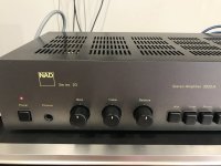
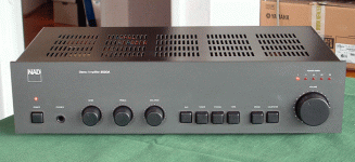
this is the most common version, the later ones like we did the FETS on is alot later and this board was used for the 'A' version, which is why im keeping my eye out for an early one as it had the series 20 front cover and MC/MM, and i want to see what the board is like for conversion of others
Attachments
- Home
- Amplifiers
- Solid State
- NAD 3020 Series 20 mk-3 MOSFET Output Conversion

