Understood, the mistake was mine when introducing the topic.What I meant was I didn't know if it was suitable at the time, not if it was any good
It was something "off the hook" on my part, sorry.
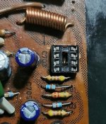
Wow! Just look at the cranked coarse frequency adjustment. That type of mechanical aid was rare and somewhat expensive in small (read DIY) quantities, back in the day. I assume it drove something like a 10 turn pot, perhaps even a reduction gear driven capacitor or coil inductor in a stable type of oscillator circuit. Such analog types of controls were about the only practical choice before the days of digital counters and generation systems.
so the base is in place and is secured down with epoxy resin.
i decided to use a micro grinder to bore out the underside to give more room for the connections
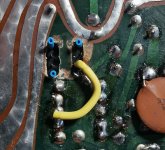
terminal 4 is soldered direct to ground
the blue heat shrinks are terminals not being used
The rest of the cables are soldered onto each pin then covered in heatshrink as a double protection in case anyone gets a bit close with a soldering iron in the future
i shal finish this tomorrow night then once all of the cables are in place i will back fill with some coloured epoxy to make it nice and stable
Its like anything you do for the fist time, its a bit suck it and see, then you find the right way
next time all the holes would be neater for example
i decided to use a micro grinder to bore out the underside to give more room for the connections
terminal 4 is soldered direct to ground
the blue heat shrinks are terminals not being used
The rest of the cables are soldered onto each pin then covered in heatshrink as a double protection in case anyone gets a bit close with a soldering iron in the future
i shal finish this tomorrow night then once all of the cables are in place i will back fill with some coloured epoxy to make it nice and stable
Its like anything you do for the fist time, its a bit suck it and see, then you find the right way
next time all the holes would be neater for example
Attachments
It looks pretty good to me 👍
Be absolutely sure you understand which pin is which 🙂 So that yellow wire is to pin 3
Be absolutely sure you understand which pin is which 🙂 So that yellow wire is to pin 3
Excellent (up).
So when you have it wired up you can test all the voltages in the socket before the chip is fitted and make sure they are correct. Also while I think about it, sockets can be tight so make sure you support it from the back when gently pressing the IC in. You don't want that neat epoxy to crack.
So when you have it wired up you can test all the voltages in the socket before the chip is fitted and make sure they are correct. Also while I think about it, sockets can be tight so make sure you support it from the back when gently pressing the IC in. You don't want that neat epoxy to crack.
Yep np. Little trick I learned a few years ago with epoxy put slightly less hard er in and it still goes off but stays flexible
so we may have a solution for the lettering and i will know on wedensday! so watch this space
@poundy that isn't the font. Let me check tomorrow. The s is different as is the eye of the d (the circle). There are slight differences.
It's close enough Alex but thanks@poundy that isn't the font. Let me check tomorrow. The s is different as is the eye of the d (the circle). There are slight differences.


New thread for the NAD 3020 with hum on right channel is now here:
https://www.diyaudio.com/community/threads/nad-3020-with-hum-on-right-channel.388397/#post-7074556
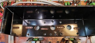
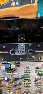
so first dry run to fit the new transistors, and ive already scratched my lovely resprayed heatsink lol, oh well i will leave it now till the final fitting.
there is quite a bit in the way in front and to the left and right of the heatsink(jumper wires) and i may move these to the underside if i feel it gives a bit more room
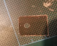
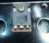
mica pad cut to size, but slightly over size where the legs are so i know there is no way they can go to ground.
and fitted, so i think this should work out ok
its a great excercise for me this, and not to be under estimated either in terms of timescales.
ive done many mechanical bespoke things in my years and have come to appreciate patience is the best freind you can have, and this is no different,what starts out as an idea, quickly becomes a mutch bigger thing than when you first start out with the idea, but its great fun.
there is quite a bit in the way in front and to the left and right of the heatsink(jumper wires) and i may move these to the underside if i feel it gives a bit more room
mica pad cut to size, but slightly over size where the legs are so i know there is no way they can go to ground.
and fitted, so i think this should work out ok
its a great excercise for me this, and not to be under estimated either in terms of timescales.
ive done many mechanical bespoke things in my years and have come to appreciate patience is the best freind you can have, and this is no different,what starts out as an idea, quickly becomes a mutch bigger thing than when you first start out with the idea, but its great fun.
Attachments
Very true is that, and also the worst part of any job is often actually beginning it.what starts out as an idea, quickly becomes a mutch bigger thing than when you first start out with the idea, but its great fun.
I beg to differ. A have several crates full of unfinished projects🙄Very true is that, and also the worst part of any job is often actually beginning it.
I’m not sure I would have spray painted the heat sink. At least not where the power transistors mount. Could be too thick (poor thermal conductivity) or have flatness issues (poor thermal contact). Polish and re-anodize - but that’s probably pricey. Even if beat up it might have been better to leave the transistor mounting surfaces alone. I might have masked off where they mount after polishing to get the burrs and nicks taken care of, then sprayed the rest if I wanted it to look new. A good black paint does help the radiation on the outer fin area.so first dry run to fit the new transistors, and ive already scratched my lovely resprayed heatsink lol, oh well i will leave it now till the final fitting.
TIP35/6? Not my first choice but they would work safely on +/-30V. And certainly more gain than 3055’s at 8A (even if by brute force). I might have gone for D1047/B817 or C5242/A1962. Might as well use the TO-3P or TO-247 to advantage. Can’t get sustained-beta types in TO-3 but you can in the flatpacks.
heatsink will be fine, its sprayed and its microns of paint thinkness
as for the transistors-my choice!
as for the transistors-my choice!
The finish just looked kind of wrinkle-y, which would be more than microns. Maybe it was that way from the factory? I have seen some pretty rough heat sinks.
The TIPs are still a better choice than 2N3055’s. High SOA above 30 V is not necessary, and they will get you there. Still have the beta droop issue, but operated that far above current rating you’ll still get a good 50 out of it, even at 4 ohms. They might need the 4.7 ish ohm base stoppers for thermal stability, though because their intrinsic resistance is pretty low to be able to pass 50A peaks. You’ll just have to monitor the idle bias under actual hard use (measure right after blasting it and make sure it settles).
The TIPs are still a better choice than 2N3055’s. High SOA above 30 V is not necessary, and they will get you there. Still have the beta droop issue, but operated that far above current rating you’ll still get a good 50 out of it, even at 4 ohms. They might need the 4.7 ish ohm base stoppers for thermal stability, though because their intrinsic resistance is pretty low to be able to pass 50A peaks. You’ll just have to monitor the idle bias under actual hard use (measure right after blasting it and make sure it settles).
will doThe finish just looked kind of wrinkle-y, which would be more than microns. Maybe it was that way from the factory? I have seen some pretty rough heat sinks.
The TIPs are still a better choice than 2N3055’s. High SOA above 30 V is not necessary, and they will get you there. Still have the beta droop issue, but operated that far above current rating you’ll still get a good 50 out of it, even at 4 ohms. They might need the 4.7 ish ohm base stoppers for thermal stability, though because their intrinsic resistance is pretty low to be able to pass 50A peaks. You’ll just have to monitor the idle bias under actual hard use (measure right after blasting it and make sure it settles).
- Home
- Amplifiers
- Solid State
- NAD 3020 project, strip down and upgrade.