I reconnected JP401, 402, 403 and all lights come on again. Tried LBT first, and draw seemed ok with a very dim bulb. Then plugged it directly into outlet and the same conditions occurred (all lights on). This latter step was so see if full line voltage is what's needed for correct operation.
My take on this is that, either a fault is present, or the unconnected stages (JP201/202 are still unconnected) trigger the protection, as they are powered off.
Edited/further thoughts:
I anyone's wondering, with JP401/402/403 connected, whatever drop occurs over the bulb makes the B+ and B++ be about 54V and 84V respectively. Under these conditions, as +/-18V is regulated and therefore correct, I can likely run it for enough time to check voltages on the input stages.
Last edited:
Any logical reason for that Bill as most manufacturers use the standard pin outs ?
It is a Japanese company but I don't understand their engineering logic other than financial so you/audio manufacturers buy their "drop-in " replacements rather than other companies products.
It is a Japanese company but I don't understand their engineering logic other than financial so you/audio manufacturers buy their "drop-in " replacements rather than other companies products.
I don't know why JRC uses reverse numbering but NAD evidently copied the pin numbering from JRC's documents. Lots of audio companies use JRC devices, mostly for cost reasons.
The only reason I can think of is that if the manufactured amplifiers are made in an automated production line it forces the manufacturer to use JRC products rather than reprogram the line and redesign the PCB,s..
I never use JRC semiconductors --not keen on them I stick with the well known "big boys ".
I never use JRC semiconductors --not keen on them I stick with the well known "big boys ".
The only reason I can think of is that if the manufactured amplifiers are made in an automated production line it forces the manufacturer to use JRC products rather than reprogram the line and redesign the PCB,s..
Sounds like a very reasonable hypothesis to me. I'm in the design software world in my real life and this rings true.
I never use JRC semiconductors --not keen on them I stick with the well known "big boys ".
I never choose JRC neither, but I see them in virtually all components I get to work on.
JRC numbers the regulator pins reversed from Fairchild. The function for a given pin physical location is the same for both however.
Bill - you checking on the possible reversal of the part gets a different weight, given this. I understand better why you'd ask.
I did closely check cross compatibility when switching to the ST Micro part - I always do, even if I'm pretty sure I'm in the clear. I call it triple-checking, and frankly often it gets to the level of quadruple-checking. Never assume.
so- it is a question of isolating the issue. 1) remove the cable from JP201/2 and the connector to the input board- this way the power supply is completely isolated. As I mentioned now check all rails for correct voltages 2) check the voltages in this situation on the Protection circuit- note this down 3) connect the cable to the input board- check voltages again Now comes the tricky part- what you need to do is apply the +/- 18v rail to the main boards whilst keeping the 62v/95v isolated. To do this you will need some small connectors from the cable to the the socket on the main amp board. 4) do the right channel first (the good channel?)- check the voltages for the transistors connected to JP402.- q202/q204, q208, q212 d212/d210 etc 5) same for the left channel this should inform you regarding the input transistors (I have replaced Q201/q203 before- they need to have similar Hfe) Once this seems ok- then connect the 62v rail to the RH channel and test the components, then same on the left- then the same for the 95v rails. when you do this check the protection circuit voltages also check the 6sk20 diodes- they can fail and Q334 a good indicator of where the problem may lie is the 1.77/-1.77 at D309/D311 check q220/q214 fail as well
Going back to this systematic approach, I've swapped these JP40x connectors, which is all that the +/-18V rails supply.
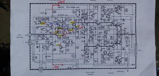
To recap (and now that the schematic is shared on the thread):
- JP401: +/-18V to the input board (with the op amps)
- JP402: +/-18V to the input stages on the main board of the R CH
- JP403: +/-18V to the input stages on the main board of the L CH
- JP201: +/-62V and +/-95V to the final stages of L CH
- JP202: +/-62V and +/-95V to the final stages of R CH
So any of these can be isolated to track faults. As I don't yet trust the higher voltage rails, and keep the amp for now through a light bulb tester (LBT), I'm first connecting the regulated +/-18V rails.
- JP401 connected (powering the input board with the op amps): all is well. Protection LED comes on for maybe 5 seconds, then relays click and only green power LED stays lit. LBT is very dimly on. This also tells me protection circuitry is well, and the voltages there seem to check out.
- JP401 + JP402: I got different results here, but last tries seem to have settled on - Protection and O/L LEDs on, then relays click and only O/L stays on. LBT dimly lit or off.
- JP401 + JP403: Protection and O/L LEDs on, no relays clicking. LBT dimly lit or off.
Hope to find some time today to check the voltages when a given circuitry is connected. I assume more bad $#!% lies ahead.
Last edited:
Keep it coming Rax I only read technical books and your thread is enjoyable reading and of course will be a great help to others with the same amplifier.
Keep it coming Rax I only read technical books and your thread is enjoyable reading and of course will be a great help to others with the same amplifier.
Thank you, Duncan, one of the main reasons I love hanging out here and fixing stuff with others thinking on it with me is not just the sense of community (which I personally thrive in, and really need), but also because I hope all this will help someone else down the road.
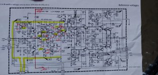
Here are some voltage measurements from both channels. This is with their respective 18V JPs connected, but 62V or 95V rails not connected. So, for instance, Q215/217 and Q216/218 don't have the correct operating point (their emitters are floating). Red ink are actual readings, blue are SM or pwdiya12 values. I used an "*" sign inconsistently, all voltage readings are 6/23 data.
I am still digesting these numbers, but one thing that's clear is that the different state of the alert LEDs with either channel connected seems to be closely reflected in the different voltage readings. If anyone ponders over these numbers and wants to share observations or thoughts, I'd appreciate it a lot.
I am typically looking for a few things when I do this:
- Vbe being a junction worth of drop (~0.6V)
- signs of shorts, open junctions (same voltage on two legs, of too wide drops across a transistor, such as C to E, etc.)
- matching conditions to what's published in SM or by others (thank you, pwdiya12).
Attachments
good work so LH channel voltages look OK can you measure the RH channel in the same manner? I would power up the left channel and check the rest of the voltages, I think they are likely to be OK. Then we can wrestle with the right channel and see what else is fried- if anything
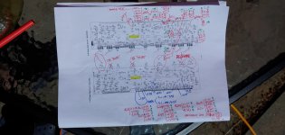
Here's a more complete, and better organized scan/annotations of readings.
Some thoughts:
- The Q201 collector node is much higher on the "faulty" channel (L) - about 10V vs 2V. That said, the schematic calls for 8.9V there, so it's a bit confusing which channel's really broken. But that "lifts" the O/L detect Q213 and Q219 to a state that generates:
- 0V out of Q220 collector
- 17V out of Q219 collector, and to the fault LEDs, respectively.
That said, I don't know how this gets reported from the L channel, as - against the schematic - in my amp only the R channel has a JP802... But if this is the case, this may explain my LED alerts and make them a bit irrelevant (given I only power one board at a time).
Attachments
Hoping to get some bench time tonight to explore this further.
A question I meant to ask for a while is - does anyone know the starting position for the adjustment pots (bias and offset)?
In other SMs I used a minimum bias position to start adjustment from, and usually a mid point for the offset adjustment, is noted. In this amp's SM, all they list is the values one should adjust for, but not where it's safe to start from. Especially having replaced some of the power transistors, this definitely needs readjustment, and cannot assume the current position is even in the ballpark.
I'm past half way through the boards in diode testing Qs, and I just can't find anything wrong with any parts in the input circuitry. The easiest way I've found to do this is to suck the solder on two of the legs and test out of circuit but in place.
I wonder if my voltage differences from one channel to another come from different DC offset adjustment points.
I'm basically done recapping too.
I wonder if my voltage differences from one channel to another come from different DC offset adjustment points.
I'm basically done recapping too.
If there are differences in the offset and you cant find any faults in the passive components then adjustment is required at the input differential pair to BALANCE out the differences due to gain differences if they are not a Super-match Pair.
If there are differences in the offset and you cant find any faults in the passive components then adjustment is required at the input differential pair to BALANCE out the differences due to gain differences if they are not a Super-match Pair.
Duncan - not talking about offset at outputs, but differences in voltages between the two channels (see my recent PDF attachments). I can't find any further faults in both active and passive components at this point. True that a whole lot of them were initially blown, but they're all replaced a bit of time ago.
A frustrating case scenario in something like this is indeed that in which something seems to be wrong (different DC voltages between L/R, see PDFs) and all parts seem to be working, no matter how many you check. I don't feel I can deem the input stages working just because I can't find faults to components, when I measure and there's distinct differences, and alarm lights act differently too.
Have you checked the diodes for leakage ?
I diode-tested some, but not all. I'm also considering replacing all zeners as I have plenty of the correct voltages. I dread shotgun repairing, but with the zeners, I'm not going to hold it against myself.
My working hypothesis is that Q202 has a "dropped" collector (2V vs 8.9V expected and 10V in the other channel), so I suspect some undue conditions either on its base biasing (R204, R206), or its collector - where I think that's there is a current source (Q206) that balances the pair driving Q202 harder or leaner, and thus providing output DC offset adjustment. For instance, per your point, Duncan, D202 is a diode I have not checked yet. This "low/2V node" condition I suppose may lift Q214/Q220 for the other unruly voltages I see.
So this is my next investigative step. I welcome feedback, of course, and thanks in advance.
- Home
- Amplifiers
- Solid State
- NAD 2200 repair