given the voltages - it looks like Q401 could be fried-also
Definitely a possibility. I'd likely use KSC1845 (pin correct), or 2N5550 (pins contortion needed). Maybe the latter as I don't think that circuitry needs anything special.
Last edited:
I use and suggest KSC1845.
I agree the SC1845 is specially designed for audio unlike the 2N5550 ,its also more sensitive with better gain for lower bias.
I agree the SC1845 is specially designed for audio unlike the 2N5550 ,its also more sensitive with better gain for lower bias.
...which we're all in agreement with (per my post right before pwdiya12):
Maybe the latter as I don't think that circuitry needs anything special.
My usual approach for medium/high-ish voltage circuitry is to go for a KSC1845 for signal path/amplification duty, or a 2N5550 if accessory circuitry (such as this Q401 is).
That circuitry not being in signal path (Q401 is part of the protection circuitry per schematic) I typically don't select a transistor specifically intended for audio, but rather a plain-jane like the 2N5550 is. So this is my thinking on this.
That said, the pin arrangement is a compelling argument to use a KSC1845.
But, going back to my checks, Q401 passes diode test on its junctions, so I deem it OK. I'll run a BE test under power on on all those Q4xy transistors (protection circuitry), to see if any shows obvious faults. C406, 407 checked out ok but I replaced them anyway, as putting the old ones back in there was too much of a pain. Used some polypropylene Wima's I like to decoupling. Really not sure what else can be wrong on that simple +/-18V PS circuitry.
Switching a bit the subject to the protection stages, on a different amp I recently worked on, the protection circuitry threw me off for a while as it was obscuring the actual faults of the amp. Once disabled, running the amp with Light Bulb Tester to protect its final transistors allowed me to find the fault fairly easily.
Not sure yet I need to do this here. To me, first order of priority is figuring out the power supply with all its rails. I welcome the wildest ideas on those funny +/-18V rails.
Last edited:
It isn't just the fact its an audio BJT its a lot more sensitive and will react quicker milliseconds count in safety circuits.
Okay-
Step 2- After all those tests including --"once in circuit it registers a high voltage" , then its obvious that this high voltage is being APPLIED to the output of the 7918 regulator .
As such cutting into its output path at various stages must logically locate the area of the fault.
Okay-
Step 2- After all those tests including --"once in circuit it registers a high voltage" , then its obvious that this high voltage is being APPLIED to the output of the 7918 regulator .
As such cutting into its output path at various stages must logically locate the area of the fault.
It isn't just the fact its an audio BJT its a lot more sensitive and will react quicker milliseconds count in safety circuits.
I get this point - "higher speed switch" - and makes sense. I'm aboard! 🙂
Okay-
Step 2- After all those tests including --"once in circuit it registers a high voltage" , then its obvious that this high voltage is being APPLIED to the output of the 7918 regulator .
As such cutting into its output path at various stages must logically locate the area of the fault.
Not sure I'm following here. With JP401, 402, and 403 unplugged (which has been the case for most of the examination of the power supplies), I don't think there's anything loading the 7918's output. This is what makes this so strange. Unless there's some strange leaking through the PCB or something, all of the circuitry from the output of the 7918 is disconnected.
Wait a sec, maybe I just got something. It may be that the floating ground of the +/-18V supply (while disconnected/by itself), vs. the ground it's seeing through the JPs, once connected, which therefore closes the +/-18V PS loop through the main ground at its respective potential is what's going on here. I think I should still see -18V at the 7918 output (just as I see +18V out of 7818) while disconnected, but it's worth giving it a shot. For instance, hook just JP401 (as op amps are currently out, so all would happen is provide this main ground) and see if the voltage readings change at all.
...hook just JP401 (as op amps are currently out, so all would happen is provide this main ground) and see if the voltage readings change at all.
Did this, and the protection circuitry seems to fall in place. I start the amp, protection light turns on, then a few seconds later I hear the relays clicking and the light goes off. At this point the voltages on the protection circuitry - all those incorrect ones - fall in place to the dot. It seems to me all that stuff works just fine.
The "high"* 7918 output doesn't change, though. As I expected it, that rail is still very "high" even when the ground for the +/-18V supply becomes tied to main ground. It was worth a shot.
Given the work I done on the bad channel - with all the faulty parts there being replaced - it may be that my only problem at this point is this ?/+#$@%$#@ -18V rail.
__________________________________________________________
*Using commas above in "high" to account for this being a negative value.
You have tried out what I and other posters have told you and you are no further forward you still have a high /overvoltage at the output of 7918.
You say you pulled the plugs between parts of the circuit attached to the 7918 output rail and nothing changed .
At this stage IMO the only logical way to go is tedious , that is as I said ---slowly disconnect each part connected to the output of the 7918 and check if the voltage returns to = -18V DC .
If need be cut into the copper first beyond the output but before you reach the the first connected part --that SHOULD read =-18V DC then solder across it if its okay ,then go to the next part and so on .
That isn't a "5 minute job " it long /slow/annoying etc but if anybody can tell you another way after --READING ALL the previous advice given to you then good luck to them .
Some faults defy every design logic answer in the book and you then have to go back to VERY basic fault tracing .
Look at fault diagrams they come in blocks -likewise trace a fault using that method --isolate-test-isolate-test even if it appears illogical .
So first question what do you get when you cut away the copper immediately after the leg is terminated ?
Unsolder the output pin of the 7918 and lift it out of the hole in the PC board. Power up and measure the voltage at the lifted output pin with respect to the 7918 ground pin. If it is still way too high, check that the 7918 is not installed backwards in the PC board.
If that turns out to be the answer Bill I will go and lie down in a quiet dark room for an hour or two.
Unsolder the output pin of the 7918 and lift it out of the hole in the PC board. Power up and measure the voltage at the lifted output pin with respect to the 7918 ground pin. If it is still way too high, check that the 7918 is not installed backwards in the PC board.
Sucking solder out seems to allow me to disconnect various parts from that node, so that's how I did this.
- With the 7918's output disconnected from the circuit (but supplied from it), I'm getting a bit under -20V out, which is a bit high (in my test fixture, I measure -17.8V out of it while applying about -29V in), but I assume this slightly elevated value may be due to the input voltage being so high, and actually a bit over its absolute max (the part I'm using, ST Micro L7918C's absolute max input DC is spec'd as 35V, while the 7818 JRC - the JRC 7918 doesn't spell this out - says 40V)
- when I connect it back, but have R422 disconnected, the voltage is maintained
- when I reconnect R422, the voltage jumps up to this high value of about -32V
R422 measures an expected 3.3k.
If that turns out to be the answer Bill I will go and lie down in a quiet dark room for an hour or two.
No, no, no, it's me who'd need to do that 🙄
Though I definitely appreciate any suggestions and thoughts, I can't imagine that being possible due to the heatsink... I can only be creative to a point in making mistakes 😀
Given all this, it seems somehow R422 lifts "up" that rail. I've looked this up in the data sheets and on, but can't find this bypass resistor anywhere - not sure what is its role. Thinking of taking it off, and seeing if things get back on track. May also put back the JRCs, as they seem to handle better the high input DC (which, for reference, in my unit amounts to about -36V).
Sucking solder out seems to allow me to disconnect various parts from that node, so that's how I did this.
- With the 7918's output disconnected from the circuit (but supplied from it), I'm getting a bit under -20V out, which is a bit high (in my test fixture, I measure -17.8V out of it while applying about -29V in), but I assume this slightly elevated value may be due to the input voltage being so high, and actually a bit over its absolute max (the part I'm using, ST Micro L7918C's absolute max input DC is spec'd as 35V, while the 7818 JRC - the JRC 7918 doesn't spell this out - says 40V)
- when I connect it back, but have R422 disconnected, the voltage is maintained
- when I reconnect R422, the voltage jumps up to this high value of about -32V
R422 measures an expected 3.3k.
R422 bypasses the 7918 and for load currents of up to 5mA, the 7918 essentially does not power the load, the resistor does. With R422 removed and the output pin of the 7918 elevated off the PC board, use your meter in current measuring mode to complete the circuit from 7918 output pin to PC board. How much current does the load circuit take from the 7918 with all connectors plugged in?
I don't know why NAD even used R422 in the circuit as it looks to be unnecessary to me. At light loads it causes the voltage to rise beyond the 7918's output. I would try moving R422 to the output of the 7918 as a load to ground. Then the voltage should settle back to -18V.
With the 7918 output pin completely isolated, I would not expect the voltage to rise above -18V even with a highish input voltage. That's a bit odd along with the rest of this issue.
Once the load current for the 7918 is determined, a resistor can be added to the input to drop the input to 30 volts or so, just to test if input voltage is an issue.
Last edited:
R422 bypasses the 7918 and for load currents of up to 5mA, the 7918 essentially does not power the load, the resistor does. With R422 removed and the output pin of the 7918 elevated off the PC board, use your meter in current measuring mode to complete the circuit from 7918 output pin to PC board. How much current does the load circuit take from the 7918 with all connectors plugged in?
I don't know why NAD even used R422 in the circuit as it looks to be unnecessary to me. At light loads it causes the voltage to rise beyond the 7918's output. I would try moving R422 to the output of the 7918 as a load to ground. Then the voltage should settle back to -18V.
With the 7918 output pin completely isolated, I would not expect the voltage to rise above -18V even with a highish input voltage. That's a bit odd along with the rest of this issue.
Once the load current for the 7918 is determined, a resistor can be added to the input to drop the input to 30 volts or so, just to test if input voltage is an issue.
Bill - thank you, I wasn't aware of this - let's call it "low current behavior" - where this switching series resistor voltage drop / voltage regulator occurs. This explains what I'm seeing quite a bit. Not sure why the 7818 behaves differently and predictably while the 7918 does this, but it doesn't quite matter ultimately. I think I'm just going to remove the resistors.
I wonder if the -36V stressed the ST parts enough to give this -20V out.
If I get correct rails at all levels after removing the resistors, given that the protection circuitry seems to be working ok, that all faulty transistors have been replaced, that a partial recap is done, I may power it up via LBT, and if all looking good, give it a real world whirl. If all checks out, complete the recap.
You have the advantage of me Bill I seem to be barred from hi-fi engine ,well it wants me to enable JS which I did --no joy and then wants to stick cookies on my PC -no I dont want that !
So I am classed as a bot and cant see the power supply circuit but your advice makes sense including adding a resistance at the output to stop slight over-voltage as that's par for the course for many of those series .
So I am classed as a bot and cant see the power supply circuit but your advice makes sense including adding a resistance at the output to stop slight over-voltage as that's par for the course for many of those series .
You have the advantage of me Bill I seem to be barred from hi-fi engine ,well it wants me to enable JS which I did --no joy and then wants to stick cookies on my PC -no I dont want that !
So I am classed as a bot and cant see the power supply circuit but your advice makes sense including adding a resistance at the output to stop slight over-voltage as that's par for the course for many of those series .
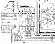
Here's the relevant part.
Attachments
The load on the 7818 appears to be greater than the load on the 7918 so the bypass resistor has less chance of pumping up the +18V output. I would remove the resistors since they can cause overvoltages and some capacitors are 25V rated. I think the load on the 7918 is less than 20mA, and most of the current is to power the NJM2043's.
duncan2, the manual is also at NAD 2200 Service Manual (Page 9 of 12) | ManualsLib
The main schematic is attached.
duncan2, the manual is also at NAD 2200 Service Manual (Page 9 of 12) | ManualsLib
The main schematic is attached.
Attachments
So,with JRC7918 ans ST L7818C I get solid +/-18V. I chose to roll back to the JRC on negative because with the LM4562s (up to +/-17V) on the input that much negative would not provide much sleep factor.
I'm tempted to hook everything back up and fire it through LBT... Any thoughts?
I feel it's mostly ready, but I will review this thread to get an overall sense of where I'm at.
I'm tempted to hook everything back up and fire it through LBT... Any thoughts?
I feel it's mostly ready, but I will review this thread to get an overall sense of where I'm at.
Last edited:
Thanks Bill & Rax for the power circuit diagram but the 7918 legs don't number the same as the standard connections -
Standard= leg 1 Earth--- leg 2 In ---leg 3 - Out
LM79XX 20110907.fm - LM7918-1306745.pdf
IC 402 has 1=out---- 2= in----3=earth ???
IC401 has different numbers than standard also ?
Standard= leg 1 Earth--- leg 2 In ---leg 3 - Out
LM79XX 20110907.fm - LM7918-1306745.pdf
IC 402 has 1=out---- 2= in----3=earth ???
IC401 has different numbers than standard also ?
- Home
- Amplifiers
- Solid State
- NAD 2200 repair