If O/P terminals are not at nearly 0 mV then problem is in this area on image.
Servo IC 201 cannot complete his mission. Check DC voltages over R107 and R108, also check diodes D101-104 and voltages on diodes and R107, R108 connection points.
No reasone to check other part of schematic and parts.

Servo IC 201 cannot complete his mission. Check DC voltages over R107 and R108, also check diodes D101-104 and voltages on diodes and R107, R108 connection points.
No reasone to check other part of schematic and parts.
Last edited:
If IC201 terminals 3 and 5 are not at 0V, you had measured voltages wrong or there are soldering problems somwhere on IC201 traces/terminals or all input ground plane is not at ground.IC201: Used the graph below to locate pins, black probe on ground red probing
Pin 1: -0.47V
Pin 2: -6.61V
Pin 3: -15.37V
Pin 4: -15.75V
Pin 5: 0V
Pin 6: -6V
Pin 7:-0.47V
Pin 8: -0.75V
If i understand this correctly the Outputs are fine no?
Also IC 201 can be dead as inverting input 6 is on lower voltage than noninverting input 5 but output is still on minus side. I presume pin 3 value is measurment error and pin 5, 6 voltages are correct.
Last edited:
Thanks for the great insight @kaameelis I’ll redo all the IC201 measurements and the other measurements you told me to do when I get home from school.
O/P Left Channel:-19.87V
O/P Right Channel:-21.6V
R107=-165mV
R108=-175mV
Solder joints are good.
D101=+2.8V on one side -165mV on other
D102=+2.8V on one side -178mV on other
D103=-2.8V on one side -165mV on other
D104=-2.81V on one side-178mV on other
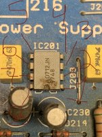
I re-did IC201 measurement here are results: I also included the photos of which pins I'm measuring.
Pin 1: -0.52V
Pin 2: -14.11V
Pin 3: 0V
Pin 4: -15.48V
Pin 5: 0V
Pin 6: -14V
Pin 7:-0.52V
Pin 8: -0.75V
Additional note: If I want to replace IC201 will a AD712JNZ work?
O/P Right Channel:-21.6V
R107=-165mV
R108=-175mV
Solder joints are good.
D101=+2.8V on one side -165mV on other
D102=+2.8V on one side -178mV on other
D103=-2.8V on one side -165mV on other
D104=-2.81V on one side-178mV on other
I re-did IC201 measurement here are results: I also included the photos of which pins I'm measuring.
Pin 1: -0.52V
Pin 2: -14.11V
Pin 3: 0V
Pin 4: -15.48V
Pin 5: 0V
Pin 6: -14V
Pin 7:-0.52V
Pin 8: -0.75V
Additional note: If I want to replace IC201 will a AD712JNZ work?
Attachments
Last edited:
Now IC201 measurement seems more reasonable.
If pin 8 is really on -0.75V (nearly not possible it can be on minus side but...) not +15V, then D213 or R243 is dead. If I remember correctly on my NAD D213 was dead.
If pin 8 is really on -0.75V (nearly not possible it can be on minus side but...) not +15V, then D213 or R243 is dead. If I remember correctly on my NAD D213 was dead.
Last edited:
Thanks for the reply @kaameelis, I’ll double check PIN 8. How would I go about testing R243 and D213. R243 is just checking resistance I think but how do I check D213.
R243- Bottom measurement=-1.693V Top measurement=-0.766V
R244- Bottom measurement=-67.9V Top measurement =-15.43
D213- Left side measurement= -0.762V Right side measurement= 0V
D214- Left side measurement= 0V Right side measurement -15.43V
so R243 is toast right ? and so is D213 ??
side note: R243 measures the same resistance as R244 at the top of the PCB haven't tested the bottom because hard to get to and currently waiting for CAPS to discharge.
and pin 8 of IC201 is definitely negative, well at least that's what my multimeter is saying.
D213 is fine cosmetically, what you see in the picture is the PCB drawing of a diode I think.
good pictures from the internal PCB's.Hello,
I’ve recently bought a not working NAD 216THX for $110 the seller stated only relay not working needs replacement, I bought the amp knowing it’s not only the relay so not a disappointment, I did replace the relay with the exact same model not newer not older, and still nothing. All the caps seem visually fine so I’ve taken some voltage readings on some jumpers that make logical sense to me as I don’t know where to get started. Just some background I’ve never worked on amps or any kind of other electronics other than making some crossovers. Here are the readings I got (this is with black probe on chassis and red probe probing and AMP powered on)
Left Ch.
J303 -19.3V
J305 -61.9V
J307 0V (makes sense it’s GND)
J309 62V
Right Ch.
J304 -21.5V
J306 -61.7V
J308 0V (makes sense it’s GND)
J310 61.8V
+Vl 61.8V
+Vr 61.8V
-Vl -61.8V
-Vr -61.8V
I’ve also included some pictures of the AMP and I found the service manual but once again, don’t know where to start.
View attachment 1205891View attachment 1205892View attachment 1205893View attachment 1205894
In such cases it is always possible that the protection mode can be triggered both by a faulty operation of the power amp stage (mostly DC offset) and by a faulty operation of the unit for protection mode itself (in this case the TA7317P)
As a first step I clean the PCB surfaces and parts and replace the small electrolytic capacitors around the TA7317 (2uF and less by foil cap - e.g. WIMA MKS) - in several cases the protection mode isn't longer present.
Isn't this the case, and no DC offset is present on output from power amp in front of relay contact, it is necessary to start troubleshooting on the protection unit - check out the attached datasheet in post #3 under
https://www.diyaudio.com/community/threads/ta7317-schematic.103030/
I think, this helps a little.
In the attached service manual from NAD216 the triangle symbol for TA7317 looks like that of the operational amplifier, which makes it very difficult to understand the kind of operation - maybe include the internal circuit from TA7317 make this more easy.
If DC on the output of power amp is present, first step is to remove the offset servo unit. Is the offset still present, reason is clearly in the power amp unit itself. If not, troubleshooting should be perform around the offset servo unit.
Last edited:
@tiefbassuebertr Thanks for the input! I think I will just replace TA7317P as it's only around 10Euro from where I'm buying it, but before I do that I also want to buy the other things I need because the shipping is costing more than the actual components, so far what I have in my cart is 1-TA7317P 1-AD712JNZ (Not sure if this will work to replace what's currently in I thought maybe you could help with telling me if it will work or not) 10-"SMD Zenerdiode 0,5W 15V Minimelf SOD-80C" and 10-"5.6k 2W 5% resistors" I'm also not sure if the zener diode is what I need, there are only 2 options on this website I will link them below.
https://elektronik-lavpris.dk/p78493/bzx83v015-zenerdiode-zpd-05w-15v-do35/
https://elektronik-lavpris.dk/p78533/bzv55c-15v-smd-zenerdiode-05w-15v-minimelf-sod-80c/
https://elektronik-lavpris.dk/p78493/bzx83v015-zenerdiode-zpd-05w-15v-do35/
https://elektronik-lavpris.dk/p78533/bzv55c-15v-smd-zenerdiode-05w-15v-minimelf-sod-80c/
On R243 right end on schematic (you call it probably bottom) must be +67V, if not, there must be some soldering, jumper or trace error, +67V did not reach R243.

So after 20 days of "shipping" my parts have arrived, I have changed R243 and D213 to no avail.
Currently im changing IC201 to see if that helps.
Currently im changing IC201 to see if that helps.
Changing IC201 didn't help either.
I redid the measurements for IC201 and they are basically identical to the previous measurements which are:
Pin 1: -0.52V
Pin 2: -14.11V
Pin 3: 0V
Pin 4: -15.48V
Pin 5: 0V
Pin 6: -14V
Pin 7:-0.52V
Pin 8: -0.75V
except pin 6 was on around -16V
These are the components I have in stock at the moment so I'll change IC202 too and see if anything happens.
1xTA7317P
1x100V 0.47uF Elec. Cap.
1x100V 1uF
1x10V 100uF
1x100V 22uF
Now, @kaameelis you said that there might be a soldering, jumper or tracer error with the +67V rail at R243 but i just don't understand where the +67V should be coming from, in the schematic it is not shown. So I don't really understand what I'm looking for, I apologise for my lack of knowledge in this subject.
I've tried to trace it back and on D203 I get -57V and on D202 I get -500mv
On D201 on positive rail I get 59.4V and on negative rail -59.4V so D201 seems fine.
On D201 on positive rail I get 59.4V and on negative rail -59.4V so D201 seems fine.
Yes, it is not shown on schematic, but I suppose it is easy to find on PCB, IC201 and IC202 are no needed to change. Find R243 on PCB and look where is going trace from this end what is not connected to IC202 pin 8. Before trace reache +67V there is somwehre break or bad soldering.Now, @kaameelis you said that there might be a soldering, jumper or tracer error with the +67V rail at R243 but i just don't understand where the +67V should be coming from, in the schematic it is not shown. So I don't really understand what I'm looking for, I apologise for my lack of knowledge in this subject.
It is possible that +67V regulator is dead. I not find in old posts you had measured +67V.

Last edited:
If I look images from internet and PCB drawing, then R243 (with red on PCB drawing) is soldered directly on +67V trace with one end, so +67V regulator is probably dead.

Last edited:
- Home
- Amplifiers
- Class D
- NAD 216 not coming out of protection mode