Hi,
I think I spot a uPC1237, protection IC in your amp. Did you read this:
https://www.diyaudio.com/community/...otection-circuit-problem.254205/#post-7461599
Solved my problem with the NAD C320. Components measured fine, but replacing the electrlytic caps around the uPC1237 brought my C320 back to life.
Hey,
There might be a problem around that area too, but first I need to figure out why the 67Volts isn't coming through.
Thanks though, I plan on recapping the whole amp anyway once I've figured out whats wrong at the moment 🙂
There might be a problem around that area too, but first I need to figure out why the 67Volts isn't coming through.
Thanks though, I plan on recapping the whole amp anyway once I've figured out whats wrong at the moment 🙂
Q201 is is OK, for Q202 correct operaiting point 5.6k R201 is too big, probably it is also OK as if Q201 is OK there is no reason what can burn Q202.
So do you think it could simply be a faulty R201?
I could possible change R201 with R202 and see what happens.
I could possible change R201 with R202 and see what happens.
+67V regulator cannot work when -67V regulator is not working, you cannot take R202 out for R201 replacement.
If you are brave enough you can replace R201 with jumper, regulator not need R201 to work, it has fuse and small noise damper function, but I am not 100% sure all is OK in +67 regulator
If you are brave enough you can replace R201 with jumper, regulator not need R201 to work, it has fuse and small noise damper function, but I am not 100% sure all is OK in +67 regulator
What if I replace R202 with 5.6Kohm resistor and replace R201 with R202 resistor, the functioning one.
Edit: Just realised no reason to do this, since using a jumper will act the same way.
What would you keep testing then in the regulator?
Edit: Just realised no reason to do this, since using a jumper will act the same way.
What would you keep testing then in the regulator?
Last edited:
I would place 200-300 ohm resistor to R201 place. 5.6K on R202 place prevents -67V regulator normal work and also +67V cannot work then.
But other way is, take R203 out, install jumper on R201 place and measure DC voltage on C210, if it is somewhere +90V or maybe higher and nothing is burned, then circuit on right side of R203 is OK and it is safe to install jumber on R 201 place and R203 back as R203 will limit current, if somethig is bad on leht side from R203.
But other way is, take R203 out, install jumper on R201 place and measure DC voltage on C210, if it is somewhere +90V or maybe higher and nothing is burned, then circuit on right side of R203 is OK and it is safe to install jumber on R 201 place and R203 back as R203 will limit current, if somethig is bad on leht side from R203.
Took out R203 put jumper in R201 spot and measured the top of C210 (negative) and it kept dropping from like 500mv and kept dropping and dropping and I decided to stop measuring around 150mv since it just kept going down.
Did you measured DC voltage? C210 not grounded pin is + pin, not - pin.
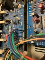
If yes, then is needed to check again all components right from R203 until R201 and traces marked with red on image.

If yes, then is needed to check again all components right from R203 until R201 and traces marked with red on image.
I’m sorry for not replying, been busy. So, at last the red led turns green however I took two steps forward then one step back. While I was measuring D204 I slipped my probe and shorted, it blew, taking some traces with it, after that I got frustrated and decided to just buy all the electrolytics, diodes and some resistors. I replaced all the electrolytics on the power supply board and replaced R201, D202, D203, D204, D205, D206, D207, C208 and C209 and repaired the traces with jumpers. I did the alignment procedure too.
Bad news the relays only clicks in sometimes and for a short amount of time.
So I have decided to do some quick measurements and did O/P and it was around 500mV on the left channel so I remembered you mentioned it before so i did these measurements "Servo IC 201 cannot complete his mission. Check DC voltages over R107 and R108, also check diodes D101-104 and voltages on diodes and R107, R108 connection points."
R107 around 12mV on each side, keeps jumping though +-4mV
R108 around 9mV on each side
D101 8.6mV anode (also jumping) 2.6V cathode (stable)
D102 9.2mV anode 2.72V cathode
D103 -2.71V anode 6.2mV cathode
D104 -2.72V anode 9.2mV cathode
With my meter set to MAX because the readings kept jumping I moved my probe around and got 3.27VDC on L in by the relay and 85.9mVDC on R in
bottom of R243 reads 68.7
bottom R244 reads -68.2
I measured IC201 maybe something can help us figure out what's wrong
The amp refuses to go out of protection mode now for some reason, hasn't happened for a while now.
IC201
Pin 1:0.805V
Pin 2:0V
Pin 3:0V
Pin 4:-15.49V
Pin 5:0V
Pin 6:keeps jumping, unable to get a good reading
Pin 7:around 0.250V
Pin 8:15.13V
The amp refuses to go out of protection mode now for some reason, hasn't happened for a while now.
IC201
Pin 1:0.805V
Pin 2:0V
Pin 3:0V
Pin 4:-15.49V
Pin 5:0V
Pin 6:keeps jumping, unable to get a good reading
Pin 7:around 0.250V
Pin 8:15.13V
Last edited:
Are +67V and -67V correctly present on amplifier boards?
At least IC201 supply voltages are now correct and it most probably works.
Problem is now related to "Pin 6:keeps jumping". This voltage is coming from left channel output, is on left board O/P terminal 500mV DC? If you measure AC on O/P terminal, what you get? Is voltage on O/P jumping more than on IC201 pin 6? Had you any oscilloscope kind of device to visualize left O/P voltage and IC201 pin 6 and pin 7 voltage? Seems like there is some kind of low frequency oscillation or some plug had bad contacts, specially JP201/JP301.
Last edited:
Unfortunately I do not have an oscilloscope. The positive and negative 67 volt on amplifier boards would that be the places marked on the photo I attached? If so then I’m only getting these voltages:
Right channel
J306:-58.8
J310:58.7
Left channel
J305:-58.7
J309:58.8
But I think I’m misunderstanding what you mean
Right channel
J306:-58.8
J310:58.7
Left channel
J305:-58.7
J309:58.8
But I think I’m misunderstanding what you mean
Attachments
+67 and -67V are going also to amp boards for input and VAS stages supply thru JP303 and JP304.
Had you sound card on PC with protected input? It can also be used as oscilloscope, but you need to be sure not to kill inputs with over voltages as amp give out more than sound card can handle. I use for over voltage protection on 2 V RMS full scale sound card input 22 times voltage divider from low ohm resistors.
Had you sound card on PC with protected input? It can also be used as oscilloscope, but you need to be sure not to kill inputs with over voltages as amp give out more than sound card can handle. I use for over voltage protection on 2 V RMS full scale sound card input 22 times voltage divider from low ohm resistors.
Last edited:
The negative and positive 67V appear at the amp boards, I’m not ready on sacrificing my sound card just yet for this (considering this is probably the only amp I’ll be repairing, time will tell)😅 maybe we can figure something out without an oscilloscope. I have recorded IC201 and O/P voltages and they seem to my eye to be similar (the pattern of change) although the voltages differ quite a lot
Probably multimeter is too slow to measure real voltage changes. Seems it is periodic oscillation and it is more difficult to find the cause of it than static problem what you had first. Oscilloscope can help here.
I understand, do you think this will be sufficient?Oscilloscope can help here.
https://www.amazon.de/-/en/gp/product/B07V67LYXF/ref=ox_sc_act_title_4?smid=A3BI8G9NTBZUKM&psc=1
Seems to be a good deal for a one time project.
- Home
- Amplifiers
- Class D
- NAD 216 not coming out of protection mode