You had very different measurements from same points. Probably somewhere is bad contact/soldering or some resistor or capacitor is faulty.
Try to measure this components on image ( measure resistance and/or capacitance when power is off, in first step no need to solder them out), are you getting stable reading?

Try to measure this components on image ( measure resistance and/or capacitance when power is off, in first step no need to solder them out), are you getting stable reading?
Can’t measure capacitance, don’t have the equipment for that but I can do the resistors:
R103: 1.486 kOhm stable
R105: 79 kOhm stable
R107: 1.486 kOhm stable
R109: The longer I hold the higher it gets but the readings started at around 960MOhms
This is still with Q101 out and D101 and D103 out. The results are taken with the resistors still in the pcb
R103: 1.486 kOhm stable
R105: 79 kOhm stable
R107: 1.486 kOhm stable
R109: The longer I hold the higher it gets but the readings started at around 960MOhms
This is still with Q101 out and D101 and D103 out. The results are taken with the resistors still in the pcb
Last edited:
Change IC201 back to original. It is very unlikely that new op amp is faulty but measurements shows clearly that there is something wrong with it or related components.
But this is definitely not the only fault in this amp. Something is generating low frequency noise but I am out of ideas what it can be, the fault is somewhere on the last image.
But this is definitely not the only fault in this amp. Something is generating low frequency noise but I am out of ideas what it can be, the fault is somewhere on the last image.
Alright well good news and bad news, so I changed out IC201 and now I get no signal and no output no input on left channel, clean. O/P at 0mv which makes me worry since shouldn’t be at like around 200mv or something. Anyway now the amp is still in protection mode so these are the basic things I’ve checked.
Left Channel:
O/P:0.3mV
J305: -58.2V
J309: 58.1V
Right Channel:
O/P: -5.67V
J306: -58.1V
J310: 58.1V
IC201:
P1: -0.311V
P2: 0
P3: 0
P4: -15.53V
P5: 0
P6: 0
P7: 0.222V
P8: 15.14V
Another observation Q201 and Q204 heat sinks are burning hot like it gets painful after holding my finger on it for 3 seconds. Don’t know if this is normal but it doesn’t seem right.
This amp seems like a gift that keeps on giving, I really hope we get this fixed your help so far has been outstanding, I just wanted to say thank you!
Now seems like IC201 is not able to adjust 0 to right channel output and protection is on because right channel O/P is not 0V, -5.67V is too much. In good condition amp 0 on O/P is very close to 0, on my amps about 20 mV, no more.
Q201 and Q204 are hot also on my amps but I did not know exactly how hot. If you can keep finger on heat sink for 3 seconds then temperature is not dangerous for transistors.
Q201 and Q204 are hot also on my amps but I did not know exactly how hot. If you can keep finger on heat sink for 3 seconds then temperature is not dangerous for transistors.
Last edited:
Not directly. I see you measured on pin 2 0V, but if O/P have -5.67V then pin 2 must have about 1/4 of this (more than -1 V), not 0. Try to find why it is 0V, are all soldering OK and so on.
Last edited:
Ok, So i have made a discovery. After not being able to find where the voltage is lost for Pin 2 of IC201 I decided to look at TA7137P and its pin voltages thinking it might get me somewhere and while doing that i moved the chip a bit so i could reach Pin 7 and it clicks out of protection. So I hooked it up to some speakers and tested it, the right channel is almost unhearable and the left the volume is fine. I didn't listen to it longer than 30 seconds as I didn't want to make something worse than it already is incase something was getting really hot or similar. WIth the amp out of protection I will do the following tests:
IC201
P1 0.806V
P2 0V
P3 0V
P4 -15.34V
P5 0V
P6 0V
P7 179.5mV
P8 14.98V
Right Channel
O/P unstable but somewhere around -15 to -22mV
Left Channel
O/P 4mV
TA7317P Can't measure, everytime i try to put my probe on a pin the amp falls in to protection again.
So, the volume problem: I put a 1khz signal through my phone (I know its not the most advanced frequency generator but it's what i have) on the
Left channel I get around 8V P-P on O/P and on Input (R301) around 300mV P-P
Right channel I get around 300mV input (R302) P-P so that's good, the input voltage is the same. On O/P i get around 30V P-P so this is where my problem is I only get 8V P-P on left channel and on Right channel i get 30V P-P.
So this is where I'm confused everything points to that the right channel has to be the one that's loud, the one that's working but that's not the case. When plugged into my speakers the right channel is barely audible while the left channel is booming with music. It's not a balance problem and I'm not mixing up amp boards, the Left Channel after some decent time of playing the output transistors heatsink is significantly hotter while the right channel is practically cold to the touch. It's definitely the amp that's the problem, i tried with another power amp for sanity check and left channel was fine.
So I am lost what should I test now ?
But this definitely feels like a step in the right direction.
Is Bridge switch in OFF position?
IC201 voltages seems OK for 0V on O/P status, all inputs are on 0 and outputs on some small positive voltage.
Try to check voltage on speaker terminals, as speaker protection relay will change amplifier amplification with negative feedback change, then if relay contact is bad you can see similar problem as you get.
Normal amplification is about 30 times, with 300mV on input you must get about 9 V on output. Wen protection relay is off or contact is not made, amplification is bigger as you get on right channel.
Original relays on NAD216/214 are weak, I had changed them on 4 amplifiers, on one amp twice. Or maybe not weak but need to be changed after 25+ years of work.
Later when problems are fixed you need to adjust amps output transistors idle current, this is explained on manual page 14 under topic Alignment Procedure. Similarly aligned idle currents will turn amp heat sink temperatures to same.
Last edited:
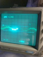
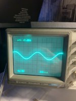
Yes, bridge is off: here are the results of the speaker terminals:
The dirty one is right terminal
The clean one is left terminal
The signal at O/P of right channel is clean unlike at terminal. The dirty signal is also present even though no signal is being passed through unlike with left terminal where if the signal is off then it’s just a straight line.
The dirty one is right terminal
The clean one is left terminal
The signal at O/P of right channel is clean unlike at terminal. The dirty signal is also present even though no signal is being passed through unlike with left terminal where if the signal is off then it’s just a straight line.
Attachments
If "The signal at O/P of right channel is clean unlike at terminal" then protection relay contact is bad. It can generate also some noise when there is no signal on input.
So, It's working and back to life again! I cleaned the contacts of the relay (will replace later) and its (the signal) clean. I wanted to thank you a lot! but ask one more question. I have recapped the whole power supply board but on the amplifier boards I have enough capacitors but none of them fit the specs all of them exceed it by a bit in varying amounts, I know that on the power supply board it doesn't matter if the specs of the caps are exceeded but on the Amp boards I'm not sure if it will change the sound or something similar.
Just a curiosity question, I feel like this amp shouldn’t be clipping with the speakers I’m using but it seems like it is, I’m using well the NAD216 and a C 162 with some Paul Carmody Pit Vipers here is the impedance sweep done by Paul carmody

And the amp starts hard clipping before hitting the middle of the volume knob when listening to some Megadeth with soft clipping on. Now I know that the volume knob isn’t linear, but is there a way I can test to see if the amp is clipping too early. Another theory I had was that my pre amp was clipping but with its specs it should not be the problem.
And the amp starts hard clipping before hitting the middle of the volume knob when listening to some Megadeth with soft clipping on. Now I know that the volume knob isn’t linear, but is there a way I can test to see if the amp is clipping too early. Another theory I had was that my pre amp was clipping but with its specs it should not be the problem.
I had changed all electrolytic capacitors (also main power capacitors) on one of my NAD214, I made THD measurements before and after, it was same. When I measured taken off capacitors, I did not find any bad capacitor. So probably with change of electrolytic capacitors you cannot improve sound of the amp.So, It's working and back to life again! I cleaned the contacts of the relay (will replace later) and its (the signal) clean. I wanted to thank you a lot! but ask one more question. I have recapped the whole power supply board but on the amplifier boards I have enough capacitors but none of them fit the specs all of them exceed it by a bit in varying amounts, I know that on the power supply board it doesn't matter if the specs of the caps are exceeded but on the Amp boards I'm not sure if it will change the sound or something similar.
Electrolytes on amp board not need to be with precise capacitance, bigger will not harm, if not bigger by 10 times.
Foil capacitors are better not to change, they can affect sound (frequency response) and stability if capacitance will be bigger or smaller and change to same value but other type will not have any effect.
My modifications, what give some results where removing soft clipping diodes and mute transistors, mainly because they where bad on some of my amps. Other mod what give some results was ground connections and ground traces modification what lowered low frequency noise more than 10 dB.
Connect oscilloscope to output and other channel to input and you will see directly what and when is clipping. NAD216 max voltage amplitude before clipping is little less than 60V (or voltage on your amp power capacitors minus about 3V)
I can give a hint on how to evaluate the general quality of a NAD216 amplifier. Give 200 Hz to 1 kHz signal to the input from good sound card and REW software with such a level that the output voltage is about 5V RMS on 8 ohm load and measure the THD with same sound card, if THD is about -100 dB then the amplifier is in good condition.
My measurement was:

My measurement was:
Last edited:
I get now also missing +/-67V problem on one of my NAD216. Braked was resistor R202 and as minus side voltage was missing, that caused also on plus side 0 voltage. But strangely protection was not on, just output had no signal.
I replaced R202 and it works again.
I replaced R202 and it works again.
- Home
- Amplifiers
- Class D
- NAD 216 not coming out of protection mode