Hi, DJQuan,
You cannot replace BC517 (darlington) with ordinary bipolar, if it is used for VBE multiplier. Bipolar has VBE of 0.65V, and darlington about 2x that = 1V3. You multiply this VBE in VBE multiplier it will give very different bias drop voltages. Some output transistor maybe not ON at all.
I have a problem once with this thing. An amp gives large DC offset, while nothing is broken. I just rearrange the bias via VBE multiplier, and everything works OK, the bias becomes below 20mV.
Hi, LC,
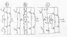
I think about making constant bias at VAS-Output connection. In figB, in top and bottom there is CCS, so the current flowing in T3-T4 will always constant. What do you think, can this be implemented in ZETA? I see ZETA uses fig.C more, where there is no constant bias due to voltage divider.
You cannot replace BC517 (darlington) with ordinary bipolar, if it is used for VBE multiplier. Bipolar has VBE of 0.65V, and darlington about 2x that = 1V3. You multiply this VBE in VBE multiplier it will give very different bias drop voltages. Some output transistor maybe not ON at all.
I have a problem once with this thing. An amp gives large DC offset, while nothing is broken. I just rearrange the bias via VBE multiplier, and everything works OK, the bias becomes below 20mV.
Hi, LC,
I think about making constant bias at VAS-Output connection. In figB, in top and bottom there is CCS, so the current flowing in T3-T4 will always constant. What do you think, can this be implemented in ZETA? I see ZETA uses fig.C more, where there is no constant bias due to voltage divider.
Attachments
Hi Lars
Good to have you back , In fact we missed your posts ,
I have just finished handpainting a pcb of a low power version of the Zeta which will have two pairs of output devices , and am just going to modify it a little to accomadate another BC547 to make T11 a darlington after reading the feedback of djQUAN as I too was planning to use BC547 here .
After I complete this I will attempt the 1000w version .
I just went through this thread and thought you will find it interesting as there is a refreance to the Zeta here .
http://www.diyaudio.com/forums/showthread.php?s=&threadid=41770&
goto=nextoldest
ah! so that explains it. and lars, yes, the neg rail mosfets are completely off. IRF9610 is the only one handling the bias along with the positive rail mosfets.
I'll try the discrete BC546 darlington transistor. I just thought that since it was just for bias, it wouldn't matter. guess it shows how nooB I am on amp design.
I'll do everything this afternoon and post about the results later. thanks for everyone's help! 😀
I'll try the discrete BC546 darlington transistor. I just thought that since it was just for bias, it wouldn't matter. guess it shows how nooB I am on amp design.
I'll do everything this afternoon and post about the results later. thanks for everyone's help! 😀
QUAN: iwould sleep a whole lot better if you could replace that 9610 with something a little bigger, or place a higher value that 15 Ohms at it's bottom. It will operate on it's power dissipation limits.
Try with 47 Ohms instead? Or 9640.
LC
Try with 47 Ohms instead? Or 9640.
LC
Zeta claiming 1000W @ 4 ohms with 90 V rails
Hi Lars Clausen,
Kindly Tell me how it is possible for ur Zeta amp to deliver 1000WRMS at 4 ohms with just 90VDC rails is it possible.
Acc to me for 1000Wrms at least 110VDC rails are required as per practical pro standards.
waiting ur response
Hi Lars Clausen,
Kindly Tell me how it is possible for ur Zeta amp to deliver 1000WRMS at 4 ohms with just 90VDC rails is it possible.
Acc to me for 1000Wrms at least 110VDC rails are required as per practical pro standards.
waiting ur response
Lars Clausen said:QUAN: iwould sleep a whole lot better if you could replace that 9610 with something a little bigger, or place a higher value that 15 Ohms at it's bottom. It will operate on it's power dissipation limits.
Try with 47 Ohms instead? Or 9640.
LC
I have gone to almost all the stores here locally and the only P channel fet I was able to encounter is the IRF9610. I'll try to raise the 10R drain resistors instead. for the pair that I'll be using at 70V rails, I'll try and look for IRFP9240.
I have tried the discrete BC546 darlington and the bias works as with the schematic values, but the DC offset is still there.
keep in mind the offset values are negative in reference to 0V ground.
I'm running out of solutions to this. I don't think the layout has something to do with the offset as the PCB is laid out almost exactly like the schematic drawing. although I'm running in a dual board config. all outputs are on one board and all low level circuitry are in another. except for the DC offset, I have no probs. SQ is still good and noise is very low. DC servo anyone?
QUAN: You DC adjustment .. does it work?
amp_man1: I realize the power spec does not take a very big rail loss into account. The DC voltage required to make 1000 W in 4 Ohms is 89.17V, i think the amp will be able to make something like 85V i 4 Ohms, with a 90V rail. So i real life the output power is slightly lower than 1000 W, more like 910 W. Raising the rail voltage is not recommended with 200V FET's as their breakdown voltage drop slightly with increasing temperature. So i will adjust the spec down to 900 W instead. If we can find a 250V P-Channel FET, instead of IRFP9240 it will be no problem to raise power back to 1000 W or higher. Fairchild maybe?????
amp_man1: I realize the power spec does not take a very big rail loss into account. The DC voltage required to make 1000 W in 4 Ohms is 89.17V, i think the amp will be able to make something like 85V i 4 Ohms, with a 90V rail. So i real life the output power is slightly lower than 1000 W, more like 910 W. Raising the rail voltage is not recommended with 200V FET's as their breakdown voltage drop slightly with increasing temperature. So i will adjust the spec down to 900 W instead. If we can find a 250V P-Channel FET, instead of IRFP9240 it will be no problem to raise power back to 1000 W or higher. Fairchild maybe?????
Use this MOSFET instead of IRFP9240 :
http://www.fairchildsemi.com/pf/FQ/FQA9P25.html
And also 250 V + devices for outputs instead of IRFP250N (like IRFP254 or maybe even a 500V device - there are many available with high power capability).
Then raise Vrails to 100 - 110V and you will have 1000 - 1100 W in 4 Ohms. Voila! 😉
http://www.fairchildsemi.com/pf/FQ/FQA9P25.html
And also 250 V + devices for outputs instead of IRFP250N (like IRFP254 or maybe even a 500V device - there are many available with high power capability).
Then raise Vrails to 100 - 110V and you will have 1000 - 1100 W in 4 Ohms. Voila! 😉
QUAN: It leads me to the possibility that your DC trimmer is not connected as shown in the schematic. It should be able to adjust the output from -1 to +1 Volt.
If it can not, it is connected wrong. Please doublecheck.
BTW what value did you use for the DC trimmer? I can see i forgot to write that value on the schematic.
If it can not, it is connected wrong. Please doublecheck.
BTW what value did you use for the DC trimmer? I can see i forgot to write that value on the schematic.
someone in this forum (sorry, forgot who you were, but you know who you are) said it is 10K. so I used 10K.
checked my PCB's. yup, they're connected as per schematic.
something I noticed:
I get ~1V across R15, and ~5V across R16. if I'm guessing right, they're supposed to be equal. and that was taken after I made the discrete darlington. (same results when I was using only a single BC546)
checked my PCB's. yup, they're connected as per schematic.
something I noticed:
I get ~1V across R15, and ~5V across R16. if I'm guessing right, they're supposed to be equal. and that was taken after I made the discrete darlington. (same results when I was using only a single BC546)
11k trimmers?? I didn't know such ones existed. But OK, that is just fine.
The BD135 / 136 transistors, what did you use exactly?
The drop over R15 and R16 should be ~ the same.
The BD135 / 136 transistors, what did you use exactly?
The drop over R15 and R16 should be ~ the same.
no, I meant R15 and R16 are originally 10k, those are fixed resistors, I used 11k.
for the BD devices, I used what you suggested. TIP31 and TIP32. C types which are 100V (same price as the lower voltage ones)
the TIP devices came from different manufacturers, did a little gain testing, the TIP32 devices have slightly higher gain than the TIP31. 31's came from fairchild semi, the other, unheard of. maybe that means I have to get another set of TIP32's? (preferably from fairchild also?)
also, the 31's have close gain specs. the 32's, very different in each of what I have.
OK, well if they have gain of something like 80 - 150 it's all OK.
Don't have to match exactly.
Try measuring with a ohm meter across each of R15 and R16. Maybe you will find something.
Don't have to match exactly.
Try measuring with a ohm meter across each of R15 and R16. Maybe you will find something.
I measured them in-circuit. they all measured 8.7k. both R15 and 16 of both channels. I'm guessing the prob could be somewhere in the input stage, since NFB should eliminate it right? and besides, the DC adj doesn't work. gonna give it a try again.......
edit: DC adj gives me +/-100mV of adj. right to each end of the trimmers.
edit: DC adj gives me +/-100mV of adj. right to each end of the trimmers.
Commentable Experienced Thoughts
ThanX Lars,
But The rail loss u r predicting doesn't hold good in Pro Environment in reality. And 90V rails are only good for 800WRMS at 4 OHMS
For a a dead sure Pro environment use IRFI9634 250V P-Channel Mosfet and IRFP264 250V N-channel Mosfet From IRF with Rails at least 100VDC to wipe out the any losses occuring to get exact 1000WRMS at 4 OHMS.
Hope this Helps in pro way.
Lars Clausen said:QUAN: You DC adjustment .. does it work?
amp_man1: I realize the power spec does not take a very big rail loss into account. The DC voltage required to make 1000 W in 4 Ohms is 89.17V, i think the amp will be able to make something like 85V i 4 Ohms, with a 90V rail. So i real life the output power is slightly lower than 1000 W, more like 910 W. Raising the rail voltage is not recommended with 200V FET's as their breakdown voltage drop slightly with increasing temperature. So i will adjust the spec down to 900 W instead. If we can find a 250V P-Channel FET, instead of IRFP9240 it will be no problem to raise power back to 1000 W or higher. Fairchild maybe?????
ThanX Lars,
But The rail loss u r predicting doesn't hold good in Pro Environment in reality. And 90V rails are only good for 800WRMS at 4 OHMS
For a a dead sure Pro environment use IRFI9634 250V P-Channel Mosfet and IRFP264 250V N-channel Mosfet From IRF with Rails at least 100VDC to wipe out the any losses occuring to get exact 1000WRMS at 4 OHMS.
Hope this Helps in pro way.
Hi Lars ,
Our friend Ampman says in another thread
(( we dont use source or drain resistors to force current sharing ,
WHICH in REALITY THEY DONT even force the slightest of Current to
share but they actually consumes lot of space on PCB. Best current
sharing is only done when amp is driven at its full output and the + temp
coeff plays its role very well there. We are not alone in the world without
source or drain resistors, K-Amps also doesnt use them in their amps.))
are emitter resistors in the Zeta only for protection purpose or they help
in current sharing also
- Home
- Amplifiers
- Solid State
- N-Channel mosfet amplifier schematic needed