Lars,
Do you refer to one side with this? (and do we stick with the original # of FETs?)
Will fans be used?
Thanks
Adam
Do you refer to one side with this? (and do we stick with the original # of FETs?)
Will fans be used?
Thanks
Adam
Commentable thoughts
Hi everybody,
A simple comment , hope u find it a little bit helping.
In our designs we use 24 IRFP250N Mosfets i.e 12 devices per rail to obtain 1000WRMS SINE Power in professional conditions.
Which ensures a good safety margin in terms of current capacity and thermal overload as well
With Regards,
Workhorse Audio Team
Amp_man_1: thanks for this information.
AdamZuf: Yes. I think cooling 1000 Watts RMS with a passive cooling system is only realistic, if you are willing to go for an amplifier the size of a cooking stove. And probably the same temperature too.
AdamZuf: Yes. I think cooling 1000 Watts RMS with a passive cooling system is only realistic, if you are willing to go for an amplifier the size of a cooking stove. And probably the same temperature too.
Hi amp Man!
I was just wondering it been too late and no sign of you on this forum topic.`
Well Ampman has some exceptional success with n ch amps have a look at his AMP for the first time here:
http://www.diyaudio.com/forums/showthread.php?s=&postid=497859#post497859
Boss all passive cooling. Now he in regular business with 64 output device amp. I am sure he will sell one to me in forthcoming years.
Have a look :
http://www.diyaudio.com/forums/showthread.php?s=&postid=497859#post497859
BTW has there been any out come with cross conduction of the earlier amp or it was just a big halla booo.
regards
Rahul
Member
Joined 2002
after running my n-channel amp on a smaller heatsink mine ran good.. then i blew it up accedently transfering it to a new heat sink.. but no damage to the amp just the fet's so FEW good think i didnt put a load on it : O )
Great little amps.. i will be ordering another board for sure..
Great little amps.. i will be ordering another board for sure..
A pair of these will handle 1KW+ with a 100CFM fan
http://www.mpja.com/productview.asp?product=14674+HS
http://www.mpja.com/productview.asp?product=14674+HS
hey lars, I have a few questions before building a zeta PCB.....
I decided to make a PCB for all the low level components only (so I could make different power output amps whenever I choose...)
judging from the schematics, I would place all the components from the input to T12 and T13 (right up to C8) on the PCB, from T14 to the last devices, all will be hardwired on the heatsink (zobel could be placed right on the speaker terminals).
the questions, which components should have thermal connection to the main heatsink or other components to maintain thermal stability?
for BD135 and 136, can I substitute MJE340/350? the BD devices are not available here.
and also, I have six IRFP460 "in stock" collecting dust. if I were to use a pair per channel, how much power could I get from them with a good safety margin?
Re: Post #78 Follow Up Questions
Hi Lars,
Did you miss seeing my follow up questions of post #78, 17 Sept 2004:
<http://www.diyaudio.com/forums/show...5794#post475794>
Regards,
John L. Males
Willowdale, Ontario
Canada
24 October 2004 05:06
Hi Lars,
Did you miss seeing my follow up questions of post #78, 17 Sept 2004:
<http://www.diyaudio.com/forums/show...5794#post475794>
Regards,
John L. Males
Willowdale, Ontario
Canada
24 October 2004 05:06
Rahul said:Hi amp Man!
I was just wondering it been too late and no sign of you on this forum topic.`
Well Ampman has some exceptional success with n ch amps have a look at his AMP for the first time here:
http://www.diyaudio.com/forums/showthread.php?s=&postid=497859#post497859
Boss all passive cooling. Now he in regular business with 64 output device amp. I am sure he will sell one to me in forthcoming years.
Have a look :
http://www.diyaudio.com/forums/showthread.php?s=&postid=497859#post497859
BTW has there been any out come with cross conduction of the earlier amp or it was just a big halla booo.
regards
Rahul
So Mr Rahul
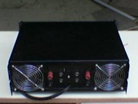
It is True That our Mustang Amp has 64 Mosfets at its output stage.
we dont use passive cooling instead of it we use twin cooling fans for active cooling.
Ans at last Holton's amp is exhibiting cross conduction even at low frequencies and also There is a chance of damaging of output devices during abrupt turn on due to imbalance in driver stage configuration.
Take alook at rear panel of our earlier model.
With Regards
Workhorse Technologies Team
Attachments
djQUAN: Mount all the IRFP's on heatsink, and also the BD135/6.
Instead of MJE340/350 use something with a little higher current. If i remember correctly the MJE's are only 500 mA or so right? (It's been 10 years+ since i have seen a datasheet on those).
Hoa about BD243 / 244 or TIP31 / TIP32, they should be available anywhere at low cost.
Instead of MJE340/350 use something with a little higher current. If i remember correctly the MJE's are only 500 mA or so right? (It's been 10 years+ since i have seen a datasheet on those).
Hoa about BD243 / 244 or TIP31 / TIP32, they should be available anywhere at low cost.
N channel amp!!
Hi Lars,
Wheres the latest schematic as you promised us with the protection ckt ,
my pcb work is stuck in the half way to implement the latest schematic.Hope things will fasten up...
Thanks
Arasuk
Hi Lars,
Wheres the latest schematic as you promised us with the protection ckt ,
my pcb work is stuck in the half way to implement the latest schematic.Hope things will fasten up...
Thanks
Arasuk
from what I remember, the local store has the TIP devices. I think these are TO220 devices. (no prob with that, terminals are just reversed.).
and yes, I also think the MJE devices are 500mA last time I checked.
about the P channel MOSFET (T14) before the neg rail output stage, is it critical to choose the correct device or could I use anything I could find?
what about using my stock of IRP460, how much power can they be used safely? I'm guessing 100W into 4 ohms for a pair per channel?
djQUAN: IRFP460, depending on which type of insulator you use, and your maximum temperature of the heat sink, you can get anything from 100 - 250 Watts out of a single pair.
Using a good silicone pad, and max. 100 degrees heat sink temperature and providing it's the old type of IRFP460 (Not the N version) you can dissipate 37 Watts in each, and with a pair that is 74 Watts, translating into 123 Watts of output power.
With max. 70 C heat sink temp the safe power increases to (59 W dissipation per device) = 198 Watts of audio power.
The very best option is the direct-on-anodized-aluminium method with no silicone insulator. Here you have a low thermal resistance of 0.45 + 0.24 C/W and with max. 100 C heat sink temp you can dissipate 72.5 W per device = 240 Watts audio power per pair.
P-Channel, you can pretty much use anything in that position. Of course not that i have tested any kind of MOSFET, but keeping capacitances at a reasonable level, and the type to regular industrial FET's, you will be OK.
arasuk: I am also working on some other improvements, and unfortunately didn't have the time to test them properly yet. So i have to wait with publication until then, next week i am going to a hifi show in Bucharest, Romania, and looking forward to meeting a lot of the DIY'ers there. After that show i will probably have the time to test the new circuits.
BTW: Thanks to the just over 2000 users who have already downloaded the schematics for the ZETA so far 🙂
All the best from
Lars
BTW: Thanks to the just over 2000 users who have already downloaded the schematics for the ZETA so far 🙂
All the best from
Lars
I just checked the local store product list, they have TIP31/32 and 31/32C.
the C version is 100V and the other is 40V. guess I'll use the 100V version. also, I looked at my stock IRFP460's. they are not the N types so they are the old ones. but they are international rectifier with same manufacturing date.
for the MOSFET insulator, I plan to use mica washers (split into very thin washers) + grease. I don't trust anodized aluminum. too thin, I might damage it easily. 🙄 😀
finally, last question, there are some resistors marked as 499R, I only use carbon films as metal films cost 20X that of carbons over here, can I use 470R or 510R? and the trimmer for adjusting DC offset, what's the resistance value of it?
thanks for all the help. gonna start on the PCB when time permits. 😀
djQUAN said:<cut>
finally, last question, there are some resistors marked as 499R, I only use carbon films as metal films cost 20X that of carbons over here, can I use 470R or 510R? and the trimmer for adjusting DC offset, what's the resistance value of it?
thanks for all the help. gonna start on the PCB when time permits. 😀
Take the 510R the differenz is minimal to 499R.
The Trimmer R22 is 10K.
Please look on my site:
- http://bauteile-fuer-die-elektronik.de/projekte/ZETA/
Spezial at
- http://bauteile-fuer-die-elektronik.de/projekte/ZETA/showimg.php?file=/00-Schaltplan/lcaudiozeta.gif
regards,
dx.master
cool site! checked out the spreadsheet. 🙂
I was thinking about using a 200R trimmer and eliminating the two 100R resistors instead.
I was thinking about using a 200R trimmer and eliminating the two 100R resistors instead.
qjQUAN: You can use the 40V as well, there will never be more than 10V across them.
470 Ohm, 510 Ohm, doesn't matter as long as you use the same all the way through.
What is the price of Carbon resistors at your place? Here they cost maybe 66% of the price of metal film resistors (both cheap BC / Philips).
Some of the resistors are critical with sound quality, here i would recommend good metalfilm resistors with copper leads. (i.e. BC Vishay series MBB0207) Some other BC Vishay types, like MRS25T actually have steel leads (!!!) Even better are carbon mass resistors, (not carbon film), but i don't know if they are available.
over here, carbon films are 25centavos each (local currency about US$0.0045 😀 , 20centavos if you buy by the 100's)
metal films here (as far as I know, they all have copper leads. 1% tol) cost about 5pesos (US$0.09) each. so 20 carbon films are one metal film. although I do intend to use metal films on the low level stuff and go to carbon films on the output stage gate resistors.........
carbon mass? I haven't heard of them (until now😀 ) or carbon composition is different?
edit:
local store does not list 2N5550, MPSA42 and MPSA92. but they sell 2N5551, MPSA43 and MPSA93. not sure if they sell them today. I have their old product list.
metal films here (as far as I know, they all have copper leads. 1% tol) cost about 5pesos (US$0.09) each. so 20 carbon films are one metal film.
although I do intend to use metal films on the low level stuff and go to carbon films on the output stage gate resistors.........carbon mass? I haven't heard of them (until now😀 ) or carbon composition is different?
edit:
local store does not list 2N5550, MPSA42 and MPSA92. but they sell 2N5551, MPSA43 and MPSA93. not sure if they sell them today. I have their old product list.
Some part of the 2000 is "noise" but I think that the community is interest in an another solid design like Leach, AKSA, Rod's stuff, Holton's etc.Lars Clausen said:BTW: Thanks to the just over 2000 users who have already downloaded the schematics for the ZETA so far 🙂
I don't mind (I don't know about the rest of the moderators) if you offer pcb's with no support (or limited maybe) and a good price and all public design. I think it's OK if you don't want to share the gerber files just the pdf's of the pattern. You can think about doing some group deal thing. This was only a suggestion.

- Home
- Amplifiers
- Solid State
- N-Channel mosfet amplifier schematic needed