Ya...probably. I like them in a passive crossover if budget is the goal. Good bang for buck. I'm quite pleased with them there, especially for woofers where other choices of capacitor get ridiculously expensive. 😎
I like the Silmics as well, I have a good selection of sizes from Digikey on a couple of orders. I redid my Luxman amp with Silmic II's wherever there were original Silmics. Next I think I'll replace some mylars in there with something better. I can't give a final judgement on my Luxman until then. I think it's a keeper anyway, now that I have work into it.
Yeah, the import duties and taxes are a little scary. Mainly because they are unkown. I asked the PartsConnexion guy if he thought there would be large duties/taxes and he said he thought there ought to be little to no charges. I dont know if I should assume he is making a sale or if this means he is marking it as low value replacement parts or something. I did some searches on line and did not come up with an answer to my particular situation but I found a few situations in which there are no charges and then others where the fees were 2-5%. That doesnt worry me. Getting charged 10% or more would not be fun.
Uriah
Uriah
I was getting worried with no answer from the Obbligatto guy and the PCB guy. Finally at least a response this morning. No quotes yet just confirmations. I think I am going to get 4 of the pcbs made and shipped to me before I go ahead and order the whole batch. I need to confirm they are built right.
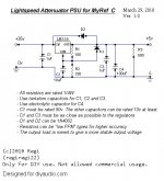
MyRef_C with integrated Lightspeed Attenuator
I am going to explain how to integrate the supplied kit with the MyRef_C using his PSU:
We will tap the +35vdc from the already rectified and smoothed out from the My_RefC PSU. You can hook up a pair of wires to the solder side of the big 10.000uF caps, this is a clear/easy place to solder. These will give us around +35vdc, so we will step it down to +5vdc using an LM338 regulator. We could use the lower-current-rated LM317, but Uriah told me that LM338 is more stable, so no place for discussion with the small price difference they have. You can mount this circuit on a little piece of stripboard or veroboard. You can even mount it point-to-point if you have enough care.
Here are some technical explanations, not necessary to succesfully build the circuit:
-An output load resistor makes any regulator happier 🙂 It keeps a constant load all the time, which turns out to give a better steady voltage. The LM338 datasheet says that it has a minimum load current ranging from 3.5 to 10mA, so a 500 Ohm resistor will suck 10mA. Plus the Lightspeed consumption, it will be enought current. R3 is using 50mW, so a 1/4W resistor will suffice.
-R1 is 100 Ohm to allow pass a 12.5mA adjustment pin current. Everywhere is recommended to put there at least 10mA. With 1.25v it consumes 15mW, so an 1/4W resistor is enough.
-R2 is 330 Ohm. I don't know how to calcule its consumption, but I know that you need a 1/2W resistor if you go above 1.6k having R1=100. SO we are fine with a 1/4W resistor.
-C1 and C3 are bypass caps, which improves regulator performance. C2 improves ripple rejection. C4 is there to provide some output capacitance and doing a bit of post-filtering, like C3. They have to be tantalum types (or even film types) because of its high-frecuency response.
The only one cap that needs to be 50v is C1. 35v would work, but too tight for long-term endurance. The others can be anything above 5v or 10v.
-D1 and D2 provide protection in case that the currents from capacitors return back and damage the regulator. 1N4002 or 1N4003 are enough.
-Uriah suggested me to use resistors with a low PPM. That means to have a low thermal drift. Output voltage will fluctuate less due thermal variations. But, in practice, with a more or less steady power consumption, this is not a big deal.
-I would go with metal film resistors because of its advantages, but it goes down to personal choice.
This circuit will provide you a first-class regulated +5vdc supply for your Lightspeed or anything else you want. You can even hook up a LED to ensure that it keeps working. The regulator will get a bit hot because of the big voltage drop, but not too much because of Lightspeed's low current consumption. You will have to attach it to an small heatsink, or to the same heatsink as the LM3886, but making sure that it's well insulated from it.
Building the Lightspeed attenuator with Uriah's matched LDRs should be trouble-free. It should take no more than a square inch veroboard. But with the supplied kits, boards are included. Hook it up to the regulated PSU and you're done. The PSU shouldn't take up more than an square inch board.
Attached files are my PSU schematics and Georgehifi Lightspeed Attenuator.
Please, comment any flaw you experienced DIYers see, any recomendation, comments, objections or insults. If we work together, we can develop the perfect partner for our Ultimate MyRef_C 😀
As Uriah points out, he's offering the Lightspeed Attenuator with this group's buy kit at a really reasonable discounted price. He is including the LDRs, the boards, the resistors and the trimmers for 30$. A nice deal for controlling the volume. You only have to put a 100k dual pot and a +5vdc supply.Another thing. I obviously sell LDRs to build the Lightspeed. I have some LDR Mount and Balance boards I sell for $8 and matched quads of LDRs I sell for $35. Normally I charge 10 shipping worldwide for any order. For anyone buying in this group buy: If you want to build a Lightpseed all you need is the board/LDRs/100k pot/ 5VDC supply. I will include the LDRs and Mount and Balance board for a total of 30. You dont have extra shipping or extra 13 you would normally pay. So saving about 23 from purchasing some other time. I will also supply the 5k pot, 200R trimmer, 4 limiting resistors free of charge. So thats another 2 dollar or so value.
I just added a column to the spreadsheet so you can place order for the LDRs, etc by marking YES or marking the number you want if you want more than 1 set.
THATS the real Ultimate BOM.
Uriah
I am going to explain how to integrate the supplied kit with the MyRef_C using his PSU:
We will tap the +35vdc from the already rectified and smoothed out from the My_RefC PSU. You can hook up a pair of wires to the solder side of the big 10.000uF caps, this is a clear/easy place to solder. These will give us around +35vdc, so we will step it down to +5vdc using an LM338 regulator. We could use the lower-current-rated LM317, but Uriah told me that LM338 is more stable, so no place for discussion with the small price difference they have. You can mount this circuit on a little piece of stripboard or veroboard. You can even mount it point-to-point if you have enough care.
Here are some technical explanations, not necessary to succesfully build the circuit:
-An output load resistor makes any regulator happier 🙂 It keeps a constant load all the time, which turns out to give a better steady voltage. The LM338 datasheet says that it has a minimum load current ranging from 3.5 to 10mA, so a 500 Ohm resistor will suck 10mA. Plus the Lightspeed consumption, it will be enought current. R3 is using 50mW, so a 1/4W resistor will suffice.
-R1 is 100 Ohm to allow pass a 12.5mA adjustment pin current. Everywhere is recommended to put there at least 10mA. With 1.25v it consumes 15mW, so an 1/4W resistor is enough.
-R2 is 330 Ohm. I don't know how to calcule its consumption, but I know that you need a 1/2W resistor if you go above 1.6k having R1=100. SO we are fine with a 1/4W resistor.
-C1 and C3 are bypass caps, which improves regulator performance. C2 improves ripple rejection. C4 is there to provide some output capacitance and doing a bit of post-filtering, like C3. They have to be tantalum types (or even film types) because of its high-frecuency response.
The only one cap that needs to be 50v is C1. 35v would work, but too tight for long-term endurance. The others can be anything above 5v or 10v.
-D1 and D2 provide protection in case that the currents from capacitors return back and damage the regulator. 1N4002 or 1N4003 are enough.
-Uriah suggested me to use resistors with a low PPM. That means to have a low thermal drift. Output voltage will fluctuate less due thermal variations. But, in practice, with a more or less steady power consumption, this is not a big deal.
-I would go with metal film resistors because of its advantages, but it goes down to personal choice.
This circuit will provide you a first-class regulated +5vdc supply for your Lightspeed or anything else you want. You can even hook up a LED to ensure that it keeps working. The regulator will get a bit hot because of the big voltage drop, but not too much because of Lightspeed's low current consumption. You will have to attach it to an small heatsink, or to the same heatsink as the LM3886, but making sure that it's well insulated from it.
Building the Lightspeed attenuator with Uriah's matched LDRs should be trouble-free. It should take no more than a square inch veroboard. But with the supplied kits, boards are included. Hook it up to the regulated PSU and you're done. The PSU shouldn't take up more than an square inch board.
Attached files are my PSU schematics and Georgehifi Lightspeed Attenuator.
Please, comment any flaw you experienced DIYers see, any recomendation, comments, objections or insults. If we work together, we can develop the perfect partner for our Ultimate MyRef_C 😀
Attachments

I forgot to quote the building webpage of the Lightspeed Attenuator. Here it is:
DIY "Lightspeed Attenuator" - Passive LDR Volume Control (audio optocouplers)
Regards,
Regi
DIY "Lightspeed Attenuator" - Passive LDR Volume Control (audio optocouplers)
Regards,
Regi
Uriah - what if I want to build A Lighter Note instead? ;P Can I buy the two $10 control boards and still get the $30 deal for the rest, or am I getting cheeky now ;P
Uriah - what if I want to build A Lighter Note instead? ;P Can I buy the two $10 control boards and still get the $30 deal for the rest, or am I getting cheeky now ;P
What are the mains differences between them? I cannot find it out from Uriah's website.
Regards,
Regi
Could anyone please explain I have noticed some unmentioned differences in the final component values on page 1 to all other designs and pdfs in this thread - C21 for example is 100nf in all doccuments, however it is listed as 22nf with no explaination?
Is this board design from twisted pear (which I can't find) identical to Russ White's latest REV? Basically I want to etch this final board from this thread myself but want to ensure it is still esentially Russ White's and the change in values were "tweaks" only so I know the board I etch is compatable (no tracking changes).
Thanks
Russ white is Twisted pearl, so both PCB's are the same. Uriah posted some pages ago an extensive list with the most important links. Included schematics and pcb layers that will be used in this group buy.Could anyone please explain I have noticed some unmentioned differences in the final component values on page 1 to all other designs and pdfs in this thread - C21 for example is 100nf in all doccuments, however it is listed as 22nf with no explaination?
Is this board design from twisted pear (which I can't find) identical to Russ White's latest REV? Basically I want to etch this final board from this thread myself but want to ensure it is still esentially Russ White's and the change in values were "tweaks" only so I know the board I etch is compatable (no tracking changes).
Thanks
In Backwards order:
Matt09 I am using gerbers given to me by Russ. Exact. Thats why I am not changing them.
Regi - differences- the improved power supply, the ability to select your impedance, the ability to balance from left to right, the current source, it just flat sounds better. I am not sharing the schematic until I come out with the microcontroller edition so lets just leave it at that with the schematic. Here is one man's opinion
New LDR preamp-Lighter Note - Club Polk
I have been working on getting them to sound even better for a few years. Dozens of different circuits, this one is the best so far and its honestly the best preamp I have ever heard and I hear that same comment from owners.
Anyway
Derwalfish, of course you can. And nearly cheeky but not quite 🙂 You must be involved in the MyREFC group buy to get this deal though. I am nearly out of Lighter Note boards and with the activity this family will endure including this group buy for the next two months I think it will be June before I buy more Lighter Note boards. I also have a few changes, like making two boards into one, correcting pinout, removing options for trimmers and replacing with regular resistors, silkscreen corrections. So it will be an entirely new board. Maybe I have 16 left right now, its a guess. I do however have over 50 of the mount and balance boards necessary to make the Lightspeed with balance option.
Regi again, Your post is correct in nearly every way. I would use higher voltage caps on the output of the LM338 and I would use a pot for R2. Changing voltage gives the option of changing impedance but now the resistor values on the mount and balance board must change to protect the LDRs. Each participant would have to make sure their LDRs dont dive below 40-50R at min/max volume. As long as that precaution is taken nearly any voltage will do. I personally dont go over about 15V. Maybe sticking with 5V like you are suggesting would be best for the most people. Easier for us to so that there is not a new explanation of the same question every day.
I would use a decent heatsink on LM338 as this is one of the big reasons that circuit is so stable. Decent being something like this Digi-Key - HS380-ND (Manufacturer - 530002B02500G)
Then you need a 100k dual log pot. I have nearly a hundred 100k dual linear pots. I can throw one of those in if you guys want. They are Alps but the linear taper will make volume come on rather fast.
Uriah
Last edited:
So many thanks you Uriah for your response. I am actually wondering if is it essential for the lightspeed to have exactly +5.00v supply? If not, we don't really need a trimmer. My resistor combination will produce 5.37v. We will need a trimmer to down it to 5.00v ONLY if tolerance of the lightspeed is quite tight. It's a way to reduce innecesary costs. What are your thoughts about that?
Are 220uF enough for the output? Shall we go for 470uF?
What a pitty with the pot issues! Would be nice to have them in the pack too. No worries then. It would be a PITA to have one of the most (if not the most) good sounding volume control having a so irregular tracking. Its very unfortable to use, at least for me.
Regards,
Regi
I think the value is fine, even 100uf is fine. I mean the voltage of the cap should be greater if anyone decides to use higher voltage. Higher voltage would allow a lower overall resistance of the LDRs. Spose they could just use a 50k pot instead if they wanted lower rtot. I get talking to much and am doing so now. Its better to keep it simple. 5.37 is fine.
Uriah
Uriah
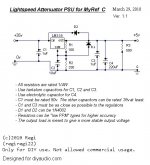
Lightspeed attenuator PSU for MyRef_C
I haven't ever seen you talking too much yet 😛 at least by the moment 😎
I am really grateful for your support, and so do other members.
I have just changed the voltage rating and capacitance value and this is the new schematic.
I hope it helps most of the builders to make a really nice integrated amplifier.
Attachments
Last edited:
Does anyone know about unmentioned changes such as C21.
First of all C21 doesn't even exists in Mauro's original design, it was added after.
These posts could clarify better why the value has been trimmed to 22nF
http://www.diyaudio.com/forums/chip-amps/134726-new-my-ref-rev-c-thread-10.html#post1778967
http://www.diyaudio.com/forums/chip-amps/134726-new-my-ref-rev-c-thread-11.html#post1784733
http://www.diyaudio.com/forums/chip-amps/134726-new-my-ref-rev-c-thread-12.html#post1792094
Regi,
Thanks for putting the effort into that. Its probably not as wonderful on the scope as a TeddyReg or otherwise 'audiophile' regulator, but it is good and it is extremely stable and its super easy and its very inexpensive. Also near impossible to mess it up.
Another nice thing is that it benefits from a seriously beefy power supply for something so small.
Uriah
Would this pot work for the attenuator?
http://www.diyaudio.com/forums/swap-meet/160327-alps-09-potentiometer.html
http://www.diyaudio.com/forums/swap-meet/160327-alps-09-potentiometer.html
Would this pot work for the attenuator?
http://www.diyaudio.com/forums/swap-meet/160327-alps-09-potentiometer.html
I don't think they will, neither as passive nor with a Lightspeed. They are a bit too high impedance for using it passive (Mauro and everyone reccomend 10k or 20k as much). And the Lightspeed needs a 100k pot, so 50k wouldn't be enough.
The vendor neither says if they are linear or log. We need the logs ones.
Tom and Dario,
Could you comment on the input cap one last time? The price difference between 1uf and 2.2uf is small and makes me want to go 2.2uf. Do you think there is an advantage at all?
Uriah
Could you comment on the input cap one last time? The price difference between 1uf and 2.2uf is small and makes me want to go 2.2uf. Do you think there is an advantage at all?
Uriah
- Status
- Not open for further replies.
- Home
- Group Buys
- MyRef_C with Ultimate BOM