Hi all,
in this thread we will discuss about building the My_Ref Fremen Edition using the Release Candidate boards.
We also discuss listening evaluations and, eventually, further improvements.
I've attached schematic, silkscreen and BOMs
To build it you will need:
in this thread we will discuss about building the My_Ref Fremen Edition using the Release Candidate boards.
We also discuss listening evaluations and, eventually, further improvements.
I've attached schematic, silkscreen and BOMs
To build it you will need:
- soldering iron
- thin solder
- tacky flux
- tweezers
- a good sight or a magnifier 😉
Attachments
Last edited:
1 - SMD parts
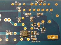
Clean boards with alcohol.
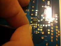
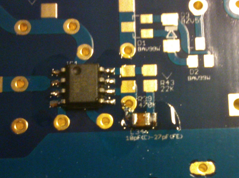
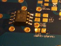
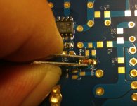
The first component we put in place is the LM318.
Apply flux to pads:

Then position the LM318 (take care to pins to pad alignment) and keep it in place with tweezers:
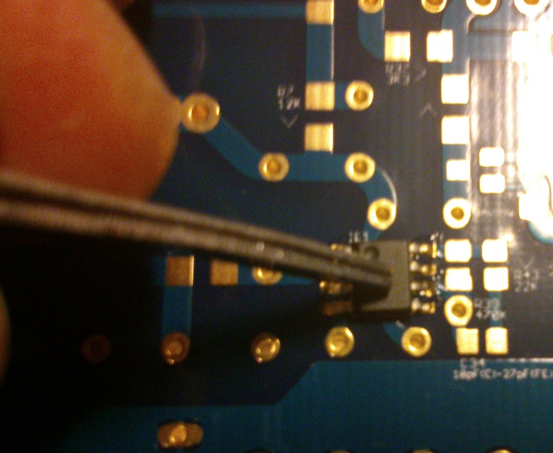
Apply the wet solder tip to one of the pins (the bottom one on the right is NC so it's a good one to use)
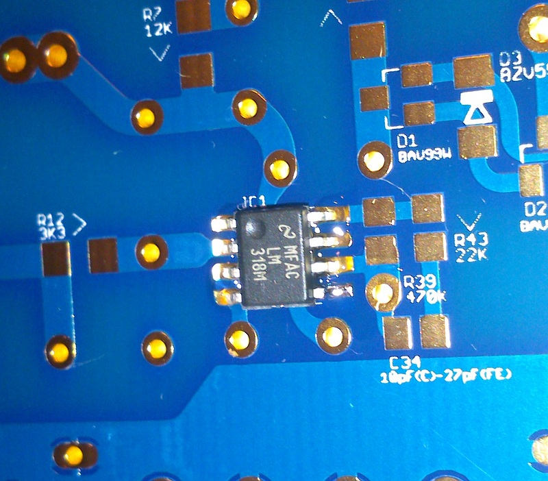
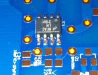
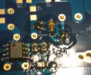
Now that the LM318 is kept in place by the soldered pin we solder all the others.
Just apply the solder and solder tip for 1-2 seconds

This should be the result:

Clean boards with alcohol.
The first component we put in place is the LM318.
Apply flux to pads:
Then position the LM318 (take care to pins to pad alignment) and keep it in place with tweezers:
Apply the wet solder tip to one of the pins (the bottom one on the right is NC so it's a good one to use)
Now that the LM318 is kept in place by the soldered pin we solder all the others.
Just apply the solder and solder tip for 1-2 seconds
This should be the result:
Attachments

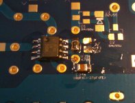
We then proceed with 0805 compensation resistors and cap, starting from C34.
Apply flux:
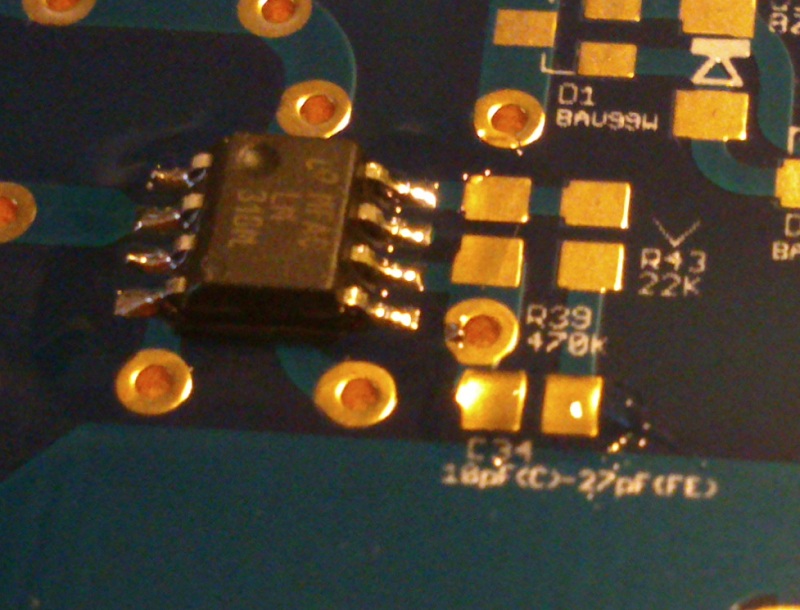
position the component and while keeping it in place with tweezers apply the wet tip to one side.

then apply solder and tip to the other end
Result
Apply flux:
position the component and while keeping it in place with tweezers apply the wet tip to one side.
then apply solder and tip to the other end
Result
Attachments


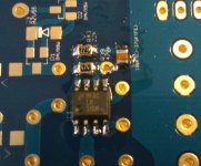
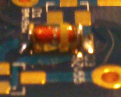
The next component will be the MELF diode D3.
As usual apply flux, keep it in place using tweezers
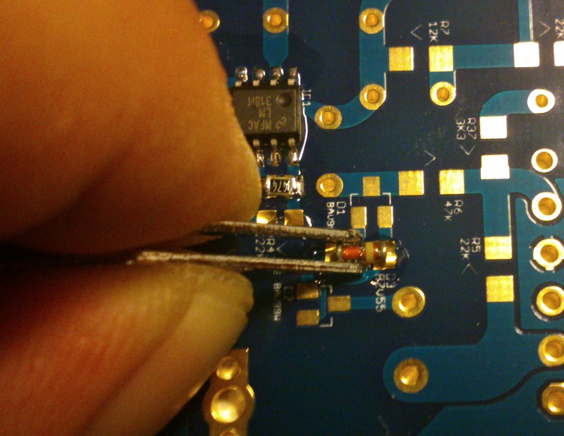
and apply the wet tip to one end (for melf you'll need a well wet tip).
Apply solder and tip to the other end.
This should be the result
Now, like we did for LM318 we proceed with D1 and D2 (flux, solder one pin while keeping the part in place with tweezers, solder the other pins)

As usual apply flux, keep it in place using tweezers
and apply the wet tip to one end (for melf you'll need a well wet tip).
Apply solder and tip to the other end.
This should be the result
Now, like we did for LM318 we proceed with D1 and D2 (flux, solder one pin while keeping the part in place with tweezers, solder the other pins)
Attachments

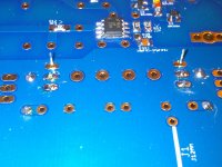
Now the we know how to solder SMD parts and made some experience, we proceed with all other resistors (pay attention to orientation)

Note that 3K3 resistors are 0805 ones soldered on 1206 pads.
Mouser don't stock in this moment 1206 3K3 Susumus so in BOM 0805 ones are indicated.
Note that 3K3 resistors are 0805 ones soldered on 1206 pads.
Mouser don't stock in this moment 1206 3K3 Susumus so in BOM 0805 ones are indicated.
Attachments
2 - Trough hole parts
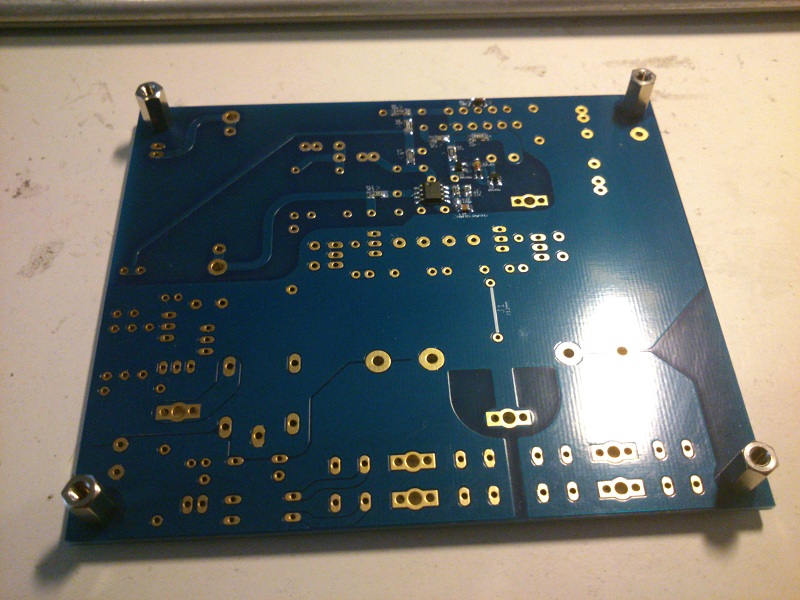
I suggest to mount standoffs before starting this phase.
Screws will stabilize board when it's reversed for soldering
The golder rule is starting from lower profile parts so we'll start from DC protection resistors.
Using pliers to bend leads helps to obtain a nice looking build.
Solder parts on both boards, alternating them, it would be easier and let parts cool.
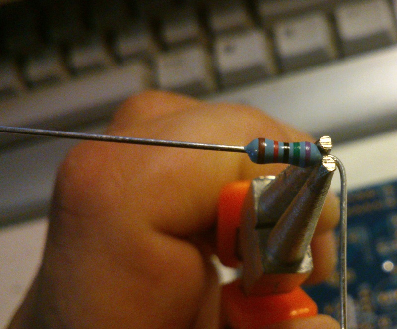
After bending leads mount the resistors in posistion and turn the board
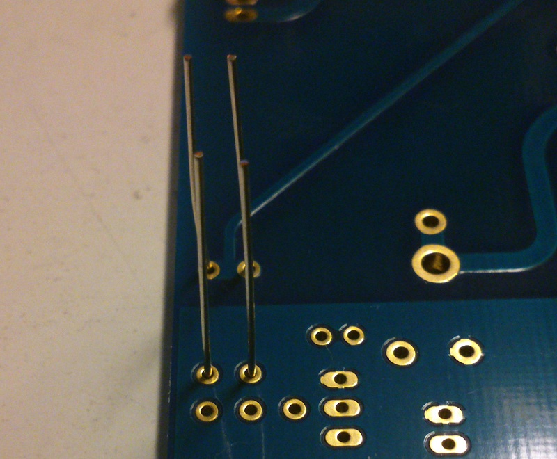
Then solder first one side of both resitors
Then proceed with other side after the second board is done.
Proceed with other 1/4W resistors
Note that I've left unsoldered thermals pads, we'll do the same for all thermals so we can solder them later with a higher soldering temperature.
If possible keep same orientation, it will look better
I suggest to mount standoffs before starting this phase.
Screws will stabilize board when it's reversed for soldering
The golder rule is starting from lower profile parts so we'll start from DC protection resistors.
Using pliers to bend leads helps to obtain a nice looking build.
Solder parts on both boards, alternating them, it would be easier and let parts cool.
After bending leads mount the resistors in posistion and turn the board
Then solder first one side of both resitors
Then proceed with other side after the second board is done.
Proceed with other 1/4W resistors
Note that I've left unsoldered thermals pads, we'll do the same for all thermals so we can solder them later with a higher soldering temperature.
If possible keep same orientation, it will look better
Attachments


Next lower profile components are the 14V zeners, bend leads first
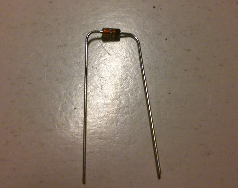
Use same tecnique used for resitors (mount parts, turn the board, solder one lead for each part, do the same on the other board, solder the remaining lead)
Then solder the 1N4001
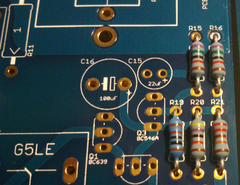
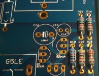
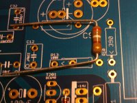
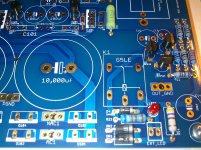
We can start with 1/2W resistors, from R10
Note in the next picture the correct orientation the gold (tolerance) band represent the point of the arrow.
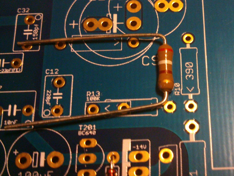
In this phase you should choose which C9/R10 arrangement to use.
I suggest the new one
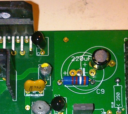
Note that Rikens have opposite orientation (tolerance red band goes opposite to the arrow)

KOA SPR orientation, note that the marking on board have same orientation of the one on resistor.
Note the thermal pad left unsolderd also for the KOA...
This is the lower profile parts soldering result
Use same tecnique used for resitors (mount parts, turn the board, solder one lead for each part, do the same on the other board, solder the remaining lead)
Then solder the 1N4001
We can start with 1/2W resistors, from R10
Note in the next picture the correct orientation the gold (tolerance) band represent the point of the arrow.
In this phase you should choose which C9/R10 arrangement to use.
I suggest the new one
Note that Rikens have opposite orientation (tolerance red band goes opposite to the arrow)
KOA SPR orientation, note that the marking on board have same orientation of the one on resistor.
Note the thermal pad left unsolderd also for the KOA...
This is the lower profile parts soldering result
Attachments
-
 22 bend zener leads.jpg136.8 KB · Views: 4,617
 -
 23 14V zeners.jpg218.1 KB · Views: 4,601
 -
 24 1n4001.jpg178.9 KB · Views: 4,604
 -
 25 half watt orientation.jpg199 KB · Views: 4,557
 -
 26 C9R10 arrangement.jpg99.1 KB · Views: 4,992
 -
 26 KOA SPR orientation.jpg153.7 KB · Views: 4,751
 -
 27 KOA thermal.jpg119.2 KB · Views: 4,526
 -
 28 lower profile result.jpg281.6 KB · Views: 4,539
Last edited:
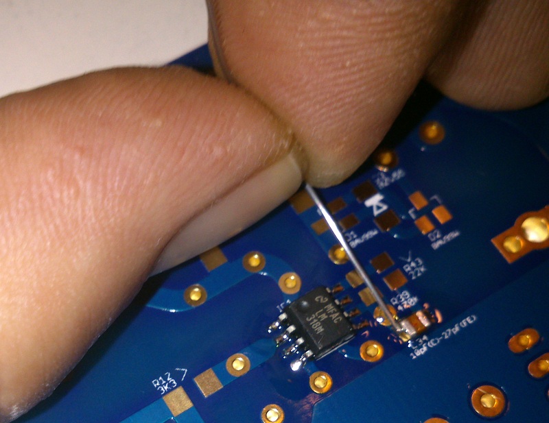
Next part to solder is the led.
Silkscreen it's not clear on led orientation, the silkscren file help us
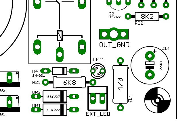
Sadly the led in BOM doesn't have the dent so we should use leads leght to identify anode and cathode, the right orientation should be this one.
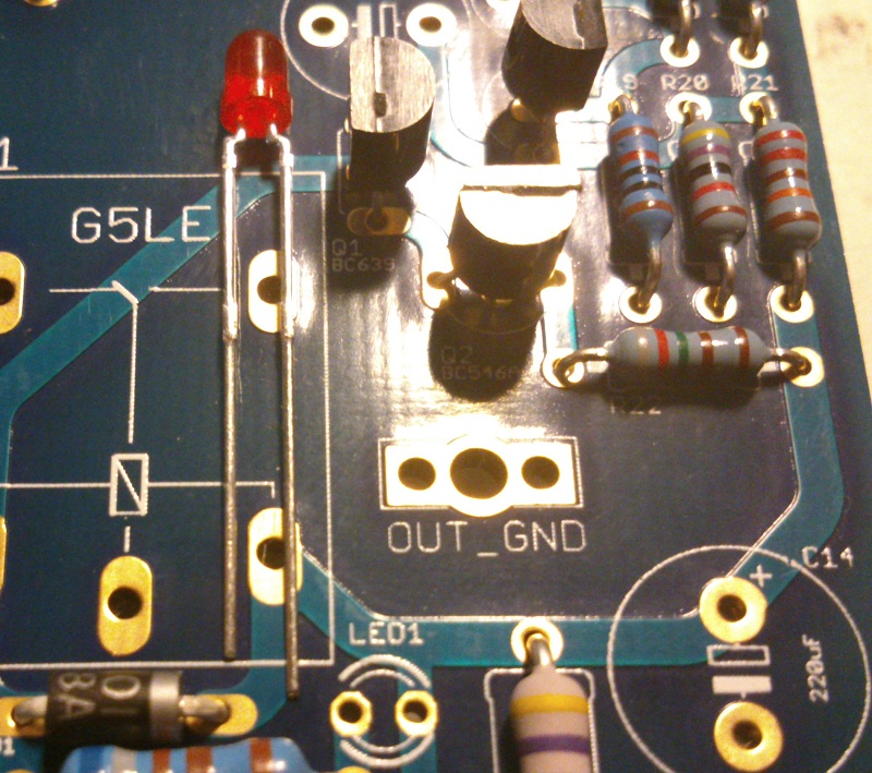
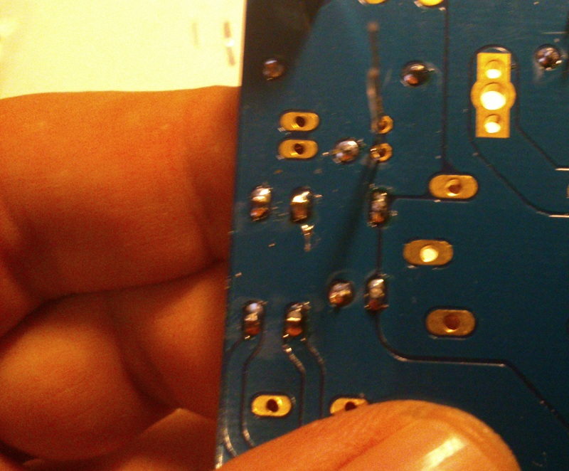
To solder it keep it in place using fingers
Silkscreen it's not clear on led orientation, the silkscren file help us
Sadly the led in BOM doesn't have the dent so we should use leads leght to identify anode and cathode, the right orientation should be this one.
To solder it keep it in place using fingers
Attachments


A further note on LED, traces of LED's pads and external LED connectors are parallel so for those that want to use the connector use same orientation.
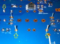
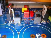
Let's pass to transitors.
 there are 2 types of BC639 in BOM: BC639-16 (regulator) and BC639G
(DC-protection)
I choose to start from DC protection ones
When soldering transistors solder one single lead for each
Then solder other leads alternating transistors so to not heat too much parts.
As usual leave thermal pads unsoldered.

Let's pass to transitors.
there are 2 types of BC639 in BOM: BC639-16 (regulator) and BC639G (DC-protection)
I choose to start from DC protection ones
When soldering transistors solder one single lead for each
Then solder other leads alternating transistors so to not heat too much parts.
As usual leave thermal pads unsoldered.
Attachments

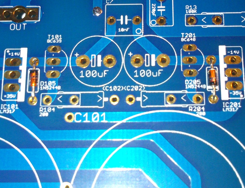
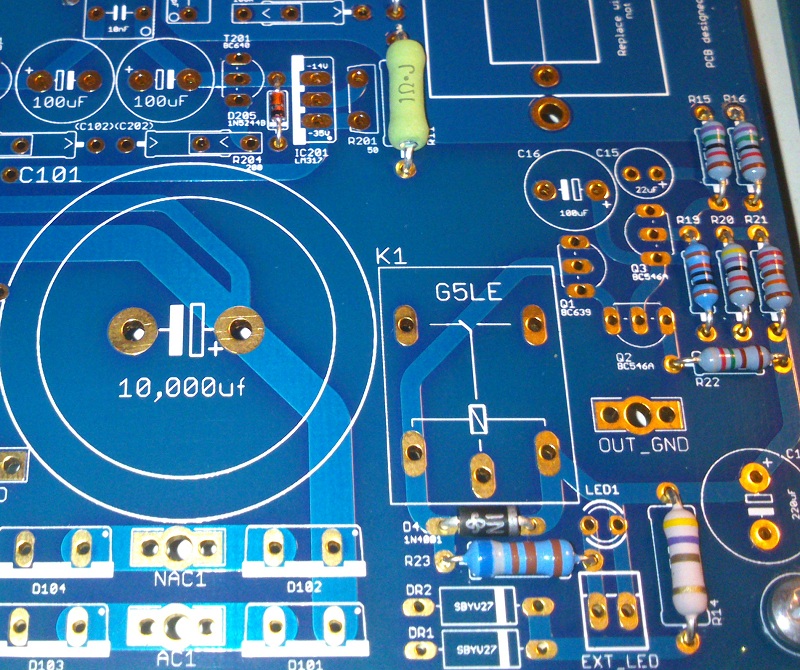
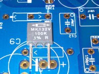
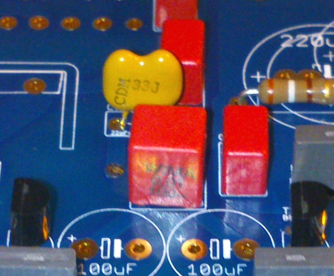
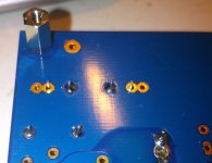
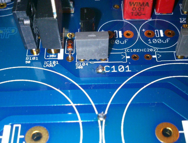
Note Caddocks MK132 orientation.
Note that R13 can be completely soldered from start even if one lead goes to ground since the bottom pad it's not directly connected to the groundplane.
R104/R204 ground leads are not soldered since on thermals.
Attachments

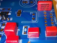
As it could be noted all markings on boards are oriented so that marked parts could be easily oriented.
See for FKP2s
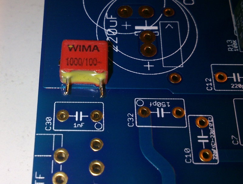
FKP2s orientation


Then solder C10
See for FKP2s
FKP2s orientation
Then solder C10
Attachments

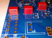

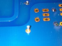
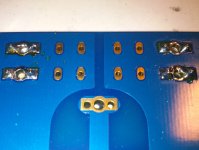
Now it's the turn of connectors.
There are two types of Molex included in BOM tin plated (EXT LED) and gold plated (IN)

Then put in place faston tabs and solder on the upper side one end
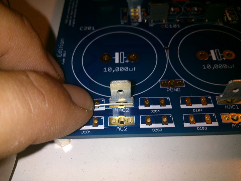
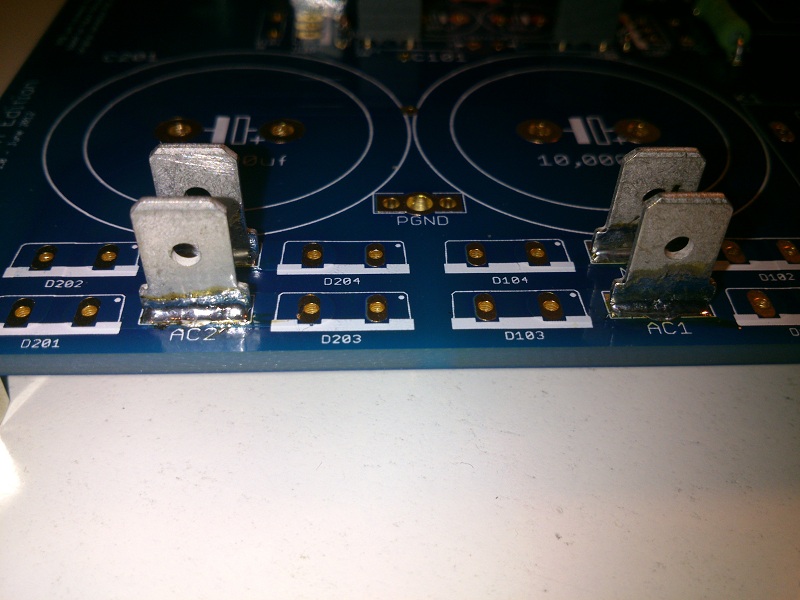
To obtain this result tabs must be heated with the soldering iron to be soldered
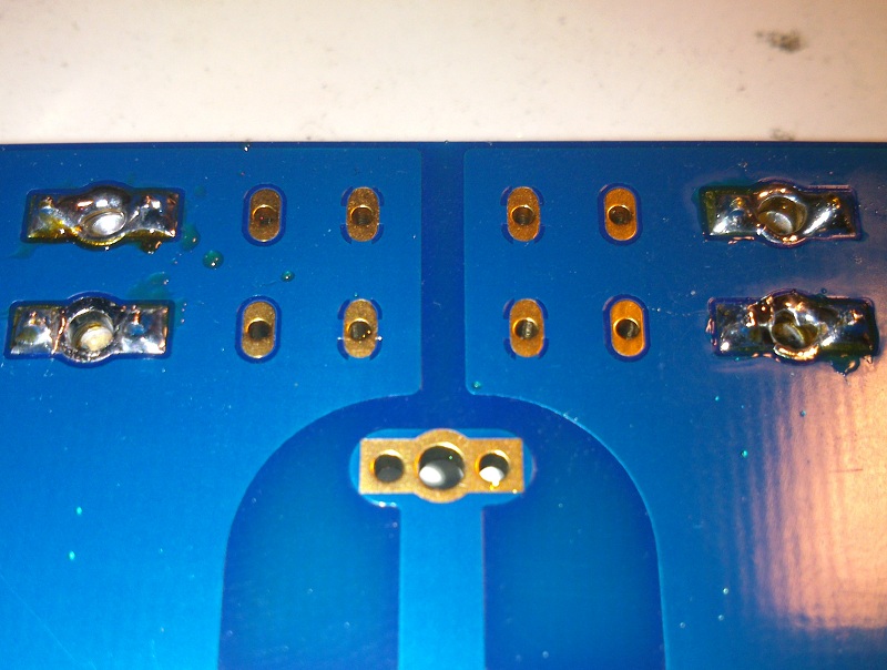
Then reverse board and solder all the tabs:
There are two types of Molex included in BOM tin plated (EXT LED) and gold plated (IN)Then put in place faston tabs and solder on the upper side one end
To obtain this result tabs must be heated with the soldering iron to be soldered
Then reverse board and solder all the tabs:
Attachments


A further note on faston tabs.
If the soldering temperature it's not enough to obtain results depicted in previous post defer their installation to when we'll raise soldering temperature to solder thermal pads.
Back on topic.
Now we solder C1 and C2:

As usual we'll leave thermal pads for later (we'll raise soldering temperature to solder all of them)
It's LM317s turn

Now MP915s
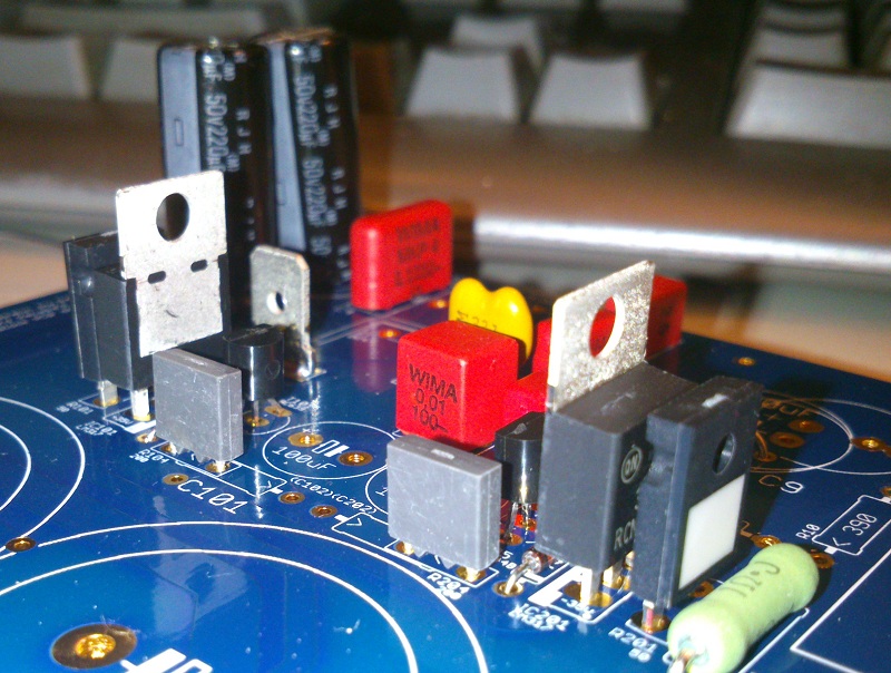
Note that ceramic pads side goes on the outside for both.
If the soldering temperature it's not enough to obtain results depicted in previous post defer their installation to when we'll raise soldering temperature to solder thermal pads.
Back on topic.
Now we solder C1 and C2:
As usual we'll leave thermal pads for later (we'll raise soldering temperature to solder all of them)
It's LM317s turn
Now MP915s
Note that ceramic pads side goes on the outside for both.
Attachments

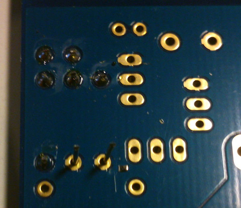
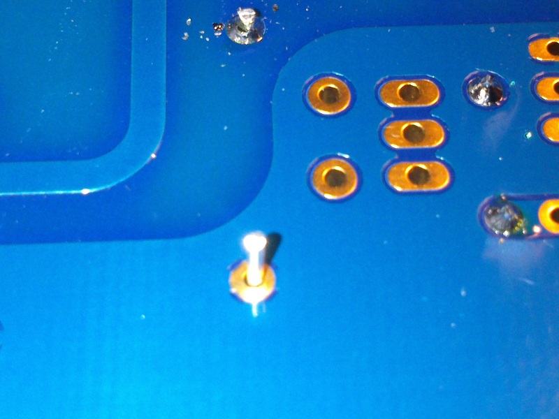
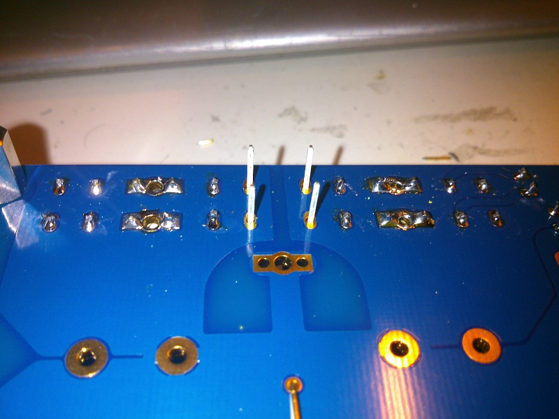
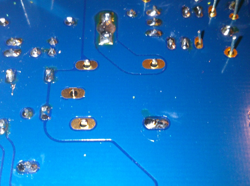
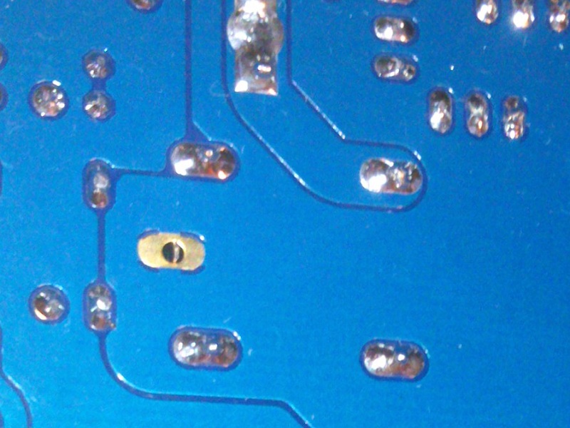
Now an essential component that could be easily forgot resulting in a not working amp or worse...
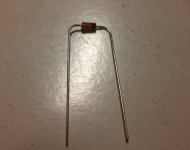
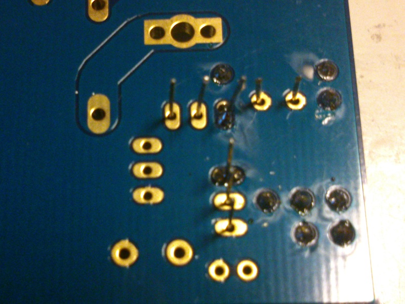
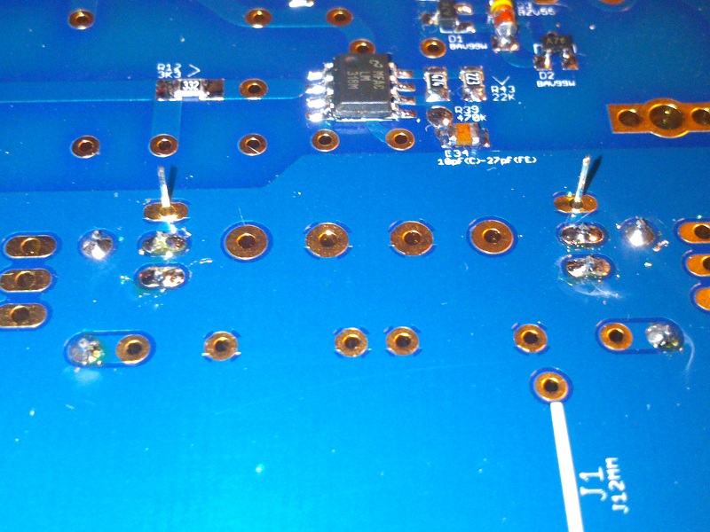
The unique jumper in the whole board (J1) which carries V-
Using pliers make a 12mm jumper:
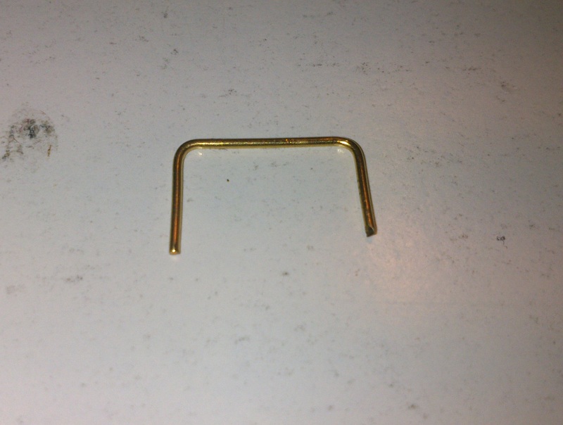
If you bought Rikens you can use their gold plated leads after trimming.
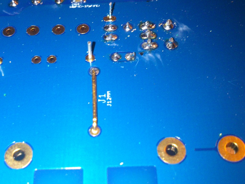
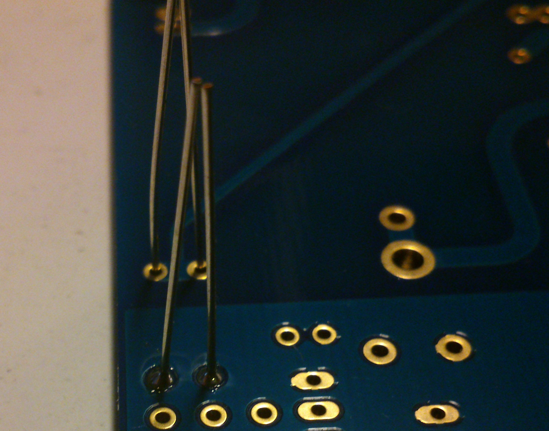
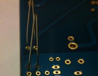
Note that J1 jumper is installed in the bottom side and soldered on the upper side.
The unique jumper in the whole board (J1) which carries V-
Using pliers make a 12mm jumper:
If you bought Rikens you can use their gold plated leads after trimming.
Note that J1 jumper is installed in the bottom side and soldered on the upper side.
Attachments


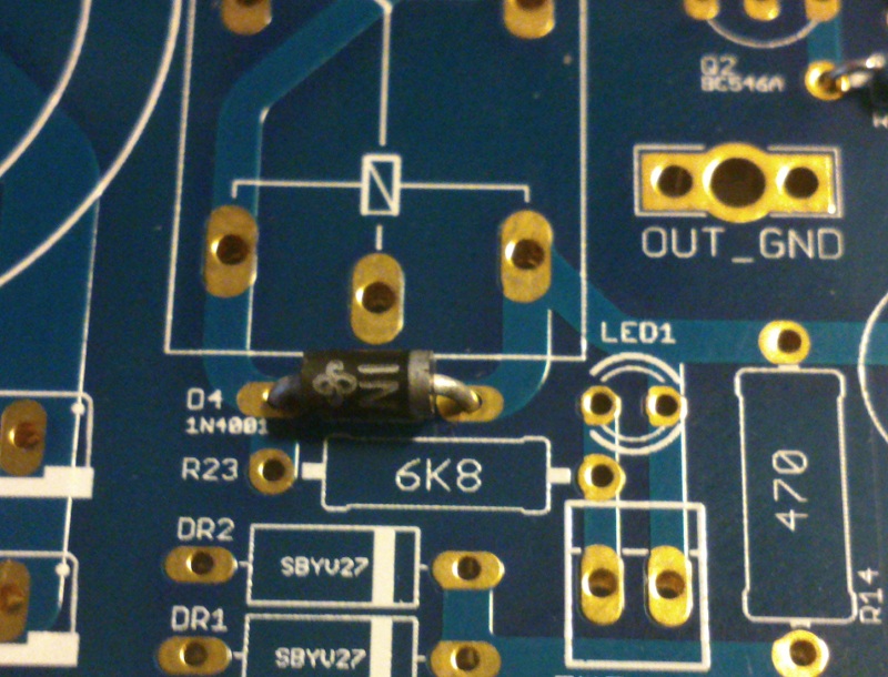
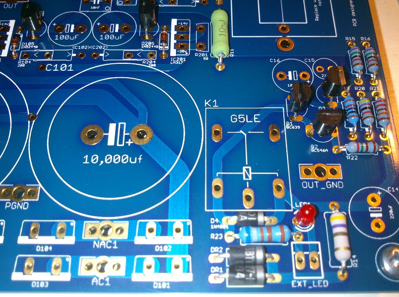
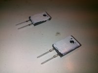
Now it's rectifiers diodes turn
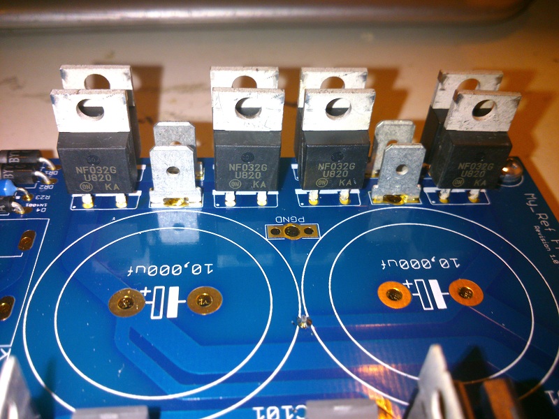
As usual thermal pads are left unsoldered.
Proceed soldering the relay, start from one or two pads while keeping it in place with fingers
Proceed with other pads leaving out the thermal one.
As usual thermal pads are left unsoldered.
Proceed soldering the relay, start from one or two pads while keeping it in place with fingers
Proceed with other pads leaving out the thermal one.
Attachments


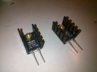
Prepare R3s with thermal compound (a thin layer)
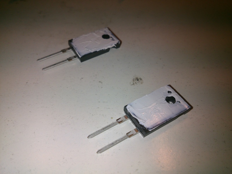
And fix them to heatsinks using M3 screws and bolts
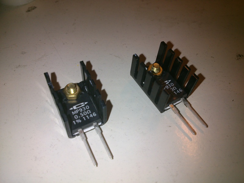
M3 screws and bolts are not indicated in BOM but can be easily sourced from any hardware store. Prefer non magnetic materials like brass.
Solder R3 in place.
Now it's time to raise soldering iron temperature (min 350°C), solder all thermal pads we left in previous steps and trim remaining leads.

Note that in the previous picture I forgot to solder relay's pad...😱
And fix them to heatsinks using M3 screws and bolts
M3 screws and bolts are not indicated in BOM but can be easily sourced from any hardware store. Prefer non magnetic materials like brass.Solder R3 in place.
Now it's time to raise soldering iron temperature (min 350°C), solder all thermal pads we left in previous steps and trim remaining leads.
Note that in the previous picture I forgot to solder relay's pad...😱
Attachments
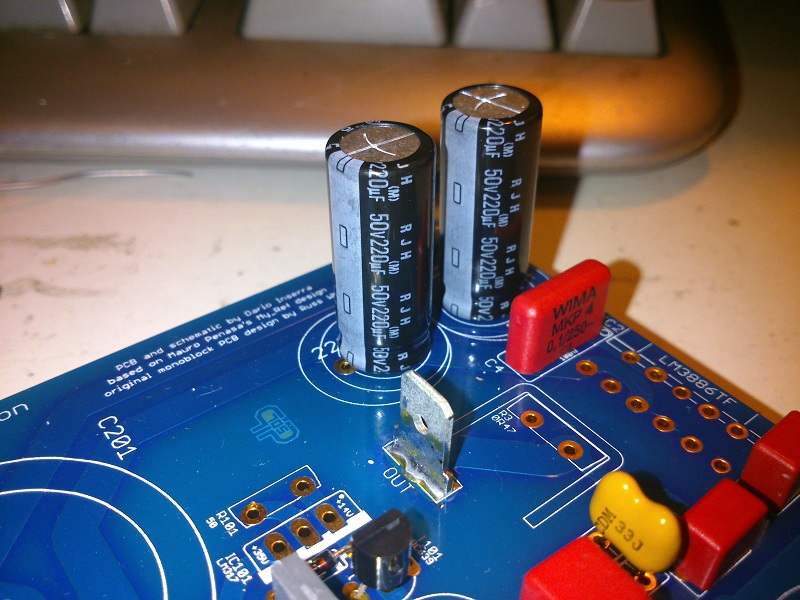
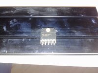
To solder LM3886TF take measures and drill heatsinks then fix the opamp to heatsinks
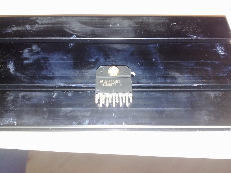
Then insert LM3886, together the heatsink, in place on board and solder a pair of pins on the upperside to keep chip in place.
Unmount opamp from heatsink, reverse board and solder all pins.
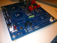
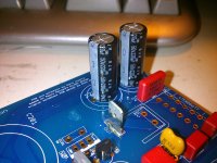
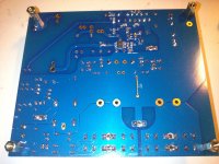
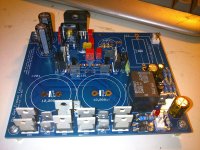
The nearly ready boards
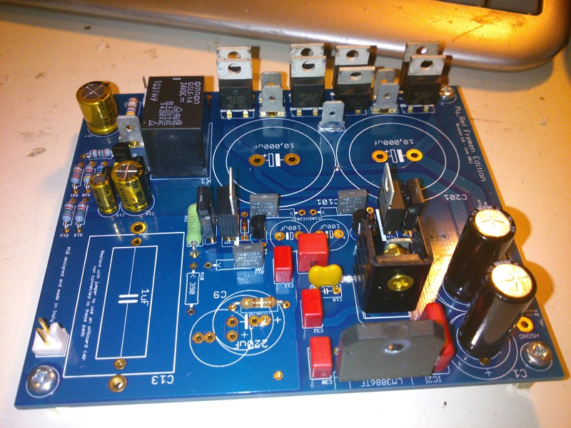
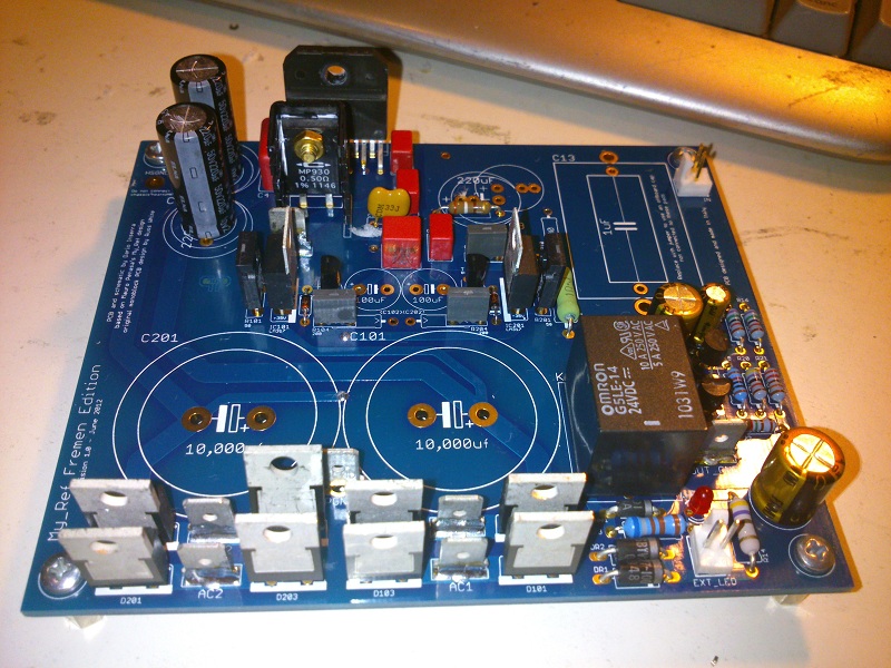
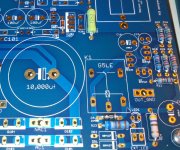
The only remaining components, not covered here are the big smoothing caps and imput cap.
Then insert LM3886, together the heatsink, in place on board and solder a pair of pins on the upperside to keep chip in place.
Unmount opamp from heatsink, reverse board and solder all pins.
The nearly ready boards
The only remaining components, not covered here are the big smoothing caps and imput cap.
Attachments

3 - Tranformers
As specced each module need a dedicated transformer to avoid hum problems.
Transformers must have double secondaries (2x25V, 2x24 also fine) and 160VA minimum rating (120VA minimum for the more efficient R-Cores).
You must find the label on transformer or its datasheet to wire them.
Selectronic R-Cores
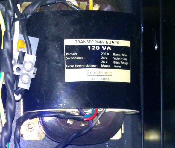
With this type of label the first color in the couple is usually hot/phase, the second neutral.
So:
AC1 Violet
NAC1 Gray
AC2 Blue
NAC2 Red
Antek AN-2225
From manifacturer datasheet:
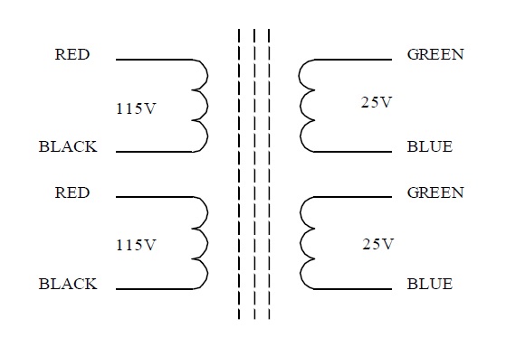
With this type of label/wiring you can't distiguish visually each secondary from the other.
One way to do it is using a multimeter to measure continuity.
Members of the same couple will have continuity.
After you identified couples wire in this way:
AC1 Green1
NAC1 Blue 1
AC2 Green 2
NAC2 Blue 2
As specced each module need a dedicated transformer to avoid hum problems.
Transformers must have double secondaries (2x25V, 2x24 also fine) and 160VA minimum rating (120VA minimum for the more efficient R-Cores).
You must find the label on transformer or its datasheet to wire them.
Selectronic R-Cores
With this type of label the first color in the couple is usually hot/phase, the second neutral.
So:
AC1 Violet
NAC1 Gray
AC2 Blue
NAC2 Red
Antek AN-2225
From manifacturer datasheet:
With this type of label/wiring you can't distiguish visually each secondary from the other.
One way to do it is using a multimeter to measure continuity.
Members of the same couple will have continuity.
After you identified couples wire in this way:
AC1 Green1
NAC1 Blue 1
AC2 Green 2
NAC2 Blue 2
Attachments


- Status
- Not open for further replies.
- Home
- Amplifiers
- Chip Amps
- My_Ref Fremen Edition RC - Build thread