measure the output offset.
Remember when the relay is triggered you must measure to the Main Audio Ground, not the isolated ground connection that has been broken by the open relay.
Remember when the relay is triggered you must measure to the Main Audio Ground, not the isolated ground connection that has been broken by the open relay.
I had the same problem like relay clicking on and off again and again in one channel, later identified I shorted out one channels speaker channel? Will it cause this problem? I had both boards singing in one speaker terminal and from another terminal the relay click on and off.
Badri
Badri
with the chipamp protection active, the chip may be switching ON/OFF. That might trigger the relay detection circuit.
Tom, You belong on this thread as much as anyone. The FE is, as I'm sure Dario would acknowledge, an extension of all the work and contributions from a whole lot of folks like yourself.
(...)
Hoping to get you and the other "Old Dudes" 🙂 onboard - hands-on soon.
Absolutely! 🙂
Dario reminded me that I needed to check orientation. To be honest, I hadn't thought to do that, although I should have. As always happens, I managed to pick the wrong orientation for both the ZN and the True Copper. Of course, I had the right orientation for the K71, so I am batting 1000.
(...)
In the end, both the TC and K71 beat the ZN for clarity and image in my system.
I'm happy you found same results. 🙂
Thanks for the reply Dario.
(...)
The LM318 was changed and unfortunately I don't have any spares of the bc639/640's.
You're welcome.
You should try to replace those transistors, you can use easy to find BD139-16/BD 140-16 in place of BC639/BC640.
It's easy to damage them while measuring.
If your relay clicks repeatedly or not at all, you most likely have other problems.
that sounds like DC detection and intermittent triggering of the relay to protect the speaker output.
Absolutely
I had both boards singing in one speaker terminal and from another terminal the relay click on and off.
H Badri,
so both channels are working if connected (one at a time) with the same speaker terminals?
H Badri,
so both channels are working if connected (one at a time) with the same speaker terminals?
Yes, Dario, will be completing it this weekend. Sings well.
Badri
The saga continues.My friend suggested I replace/resolder D1 which was slightly of square which I did this evening and having powered up all voltages appear ok and there is 4.3mv offset and 14.58v across the relay diode.It has been sat on the workbench/dining table for the past 30/40 mins without anything untoward happening.I think it might be good to go 😀


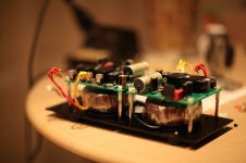
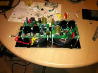
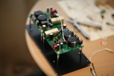
I have great news too, finally got the caps and almost finished the case, only the front panel is left now. Works fine, the case is barely warm (ambient is +27) after an hour of movies on moderate volume with a closed lid.
One board is soldered with Tackmans instead of smd part and shows 0.8mv offset. Other uses Vishay smd resistors and cement 0R47 (for testing purposes only) shows 4.5mv offset, still acceptable, though not sure what caused the difference.
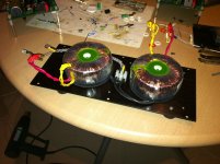
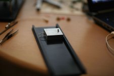
Chip goes to solid aluminum plate 16x50x50 that is tightly attached to the case, thermal grease between them, no bolts used here 🙂
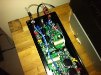
Remains of Kimber 4TC used from the boards to binding posts. Used CMC silver plated RCAs (actually didn't like them) with solid silver 0.3mm wire for the signal.
Will add 0.3-1mm aluminum shielding later between the boards and toroids.
What else to say, amp is dead silent and is my first diy PA! thanks to all guys here for helping me, especially Dario, AndrewT, Bob 🙂
One board is soldered with Tackmans instead of smd part and shows 0.8mv offset. Other uses Vishay smd resistors and cement 0R47 (for testing purposes only) shows 4.5mv offset, still acceptable, though not sure what caused the difference.
Chip goes to solid aluminum plate 16x50x50 that is tightly attached to the case, thermal grease between them, no bolts used here 🙂
Remains of Kimber 4TC used from the boards to binding posts. Used CMC silver plated RCAs (actually didn't like them) with solid silver 0.3mm wire for the signal.
Will add 0.3-1mm aluminum shielding later between the boards and toroids.
What else to say, amp is dead silent and is my first diy PA! thanks to all guys here for helping me, especially Dario, AndrewT, Bob 🙂
Attachments
-
 IMG_0207.jpg387.4 KB · Views: 410
 -
 IMG_0220.jpg393 KB · Views: 190
 -
 IMG_7967.jpg218.5 KB · Views: 201
 -
 IMG_7956.jpg253.8 KB · Views: 241
 -
 IMG_7946.jpg176.7 KB · Views: 245
 -
 IMG_0208.jpg389.8 KB · Views: 364
 -
 IMG_7922.jpg118.9 KB · Views: 371
 -
 IMG_7902.jpg177.9 KB · Views: 387
 -
 IMG_7897.jpg166.2 KB · Views: 392
 -
 IMG_7971.jpg243.1 KB · Views: 225
Last edited:
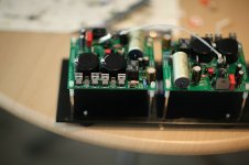
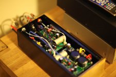
Great to hear that Dtses. You have a nice enclosure and also very pro pictures.
The two large capacitors looks a bit strange to me. What kind they are ?
The two large capacitors looks a bit strange to me. What kind they are ?
thanks!
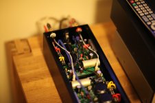
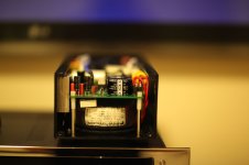
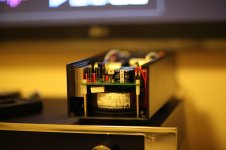
Unfortunately this is the only lens I have now so looks a bit blurred, other pics are made with iphone 🙂
Caps are Panasonic 35x20mm, weird size for me as well, I ordered them from Germany, so hope that these are genuine.
Unfortunately this is the only lens I have now so looks a bit blurred, other pics are made with iphone 🙂
Caps are Panasonic 35x20mm, weird size for me as well, I ordered them from Germany, so hope that these are genuine.
Attachments
Last edited:
I see you are using 2x18v AC this gives you 25v after rectification theoretically. Dont you think your caps are on the limit on their working voltage ?
I'm always trying to use caps al least 5 v over the voltage.
I'm always trying to use caps al least 5 v over the voltage.
Guys, are you planning GB for final version of the amplifier?
If yes- when will it be (approx ) ?
If yes- when will it be (approx ) ?
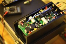
That's one of the best uses of a small chassis I have seen. Classic simplicity !
Was interested to see if there was any interference/hum with the toroids being so close and parallel. Sounds like it worked just fine. Of course I think the braided leads are great and you have a super clean and efficient wiring layout.
Are you planning to include some bottom to cover convection ventilation? May not be necessary but wouldn't hurt.
Beautiful build and thanks for sharing.😎
P.S. Please post at least a link on the chipamp photo gallery.
Last edited:
I see you are using 2x18v AC this gives you 25v after rectification theoretically. Dont you think your caps are on the limit on their working voltage ?
I'm always trying to use caps al least 5 v over the voltage.
same rule for me. Unfortunately no space here for 40-50v caps. There were several alternatives to these PANAS that also fit the chassis - Elnas and Mallory, though I stayed with Panas more because of the price and that parcels from China should be waited for more than a month.
So I've got very close to 25VDC on them, 24.5-24.9VDC depending on the mains to be precise. Hope they could withstand that voltage for some time, alternatively I could always replace them later as there are options. Btw, I'm not planning to use the amp for many years, perhaps it would be sold later as I've already had an idea of ideal FE where four monos are placed in the same chassis (standard size now) and that would be a wonderful solution for biamping 🙂
That's one of the best uses of a small chassis I have seen. Classic simplicity !
thanks for such a pleasant comment, Bob!
Are you planning to include some bottom to cover convection ventilation? May not be necessary but wouldn't hurt.
there are no ventilation in this case at all! I know it's bad, but it feels hardly warm (chip, solid aluminum plate, both walls of the case) after a movies is played. Of course, I'll need more thorough and loud testing, but I was very surprised with these results. My plan is to add ventilation anyway, it would be done via laser by adding several long holes on both lids.
P.S. Please post at least a link on the chipamp photo gallery.
will do once i finish case, the front panel in chrome is still to come.
I have great news too, finally got the caps and almost finished the case, only the front panel is left now.
Great! 🙂
I still think it's an extreme/borderline build but very well executed 😉
I'll wait your listening impressions...
Guys, are you planning GB for final version of the amplifier?
If yes- when will it be (approx ) ?
It depends on builders feedback and build rate...
So far I would say in the first 2013 quarter.
- Status
- Not open for further replies.
- Home
- Amplifiers
- Chip Amps
- My_Ref Fremen Edition RC - Build thread