It's correct but it's a very low value resistor, 0.47 Ohm, maybe it's for this reason that you MM see a short.
Oh snap, I seem to have misread the schematic... I thought it was 47 Ohms.
It's a very important step... if you fried the LM318 one of the reasons could be a wrong part in the wrong position...also some parts could have been damaged.
I just compared all the parts between the two boards again and they're definitely all the same... I guess one of them must be damaged, then. Is there any chance a damaged C30 could cause this behavior? I did accidentally touch that one with the soldering iron and it looks pretty roughed up, but when I removed and measured it it measured as a 1nF cap as it should, so I re-installed it...
Did you see the Chip Quik video on YouTube?
https://www.youtube.com/watch?v=FTQqjggeklo
It shows how to remove the excess desoldering alloy with ease.
Well, I didn't use chip quik to desolder the LM3886 - I just cut the leads, pulled out the pins (easy) and then wicked the solder out from the holes (not very easy, at least not on the ones connected to the ground plane). Desoldering the LM318 was a matter of seconds (as shown in the video you linked), the 3886 is a different animal though because it's through-hole. That's why I'm really dreading having to remove it again.
Last edited:
Don't worry about wicking the solder from the vias, there is an easy way to prep them for a new part. Just heat the pad with your soldering iron and when the solder flows poke a tooth pick through the hole and remove the iron. The solder won't stick to the wood. When it "freezes" remove the toothpick and you have a clear "pre-tinned" via.
Don't worry about wicking the solder from the vias, there is an easy way to prep them for a new part. Just heat the pad with your soldering iron and when the solder flows poke a tooth pick through the hole and remove the iron. The solder won't stick to the wood. When it "freezes" remove the toothpick and you have a clear "pre-tinned" via.
Thanks for the tip - I'd tried something similar with a clipped lead with no success but hadn't thought to use something that wouldn't stick to the solder, like wood. I'll try it next time I have to free some holes of solder!
Also, it seems that a new D2 (or maybe the cleaning that followed its installation?) has fixed my problems with the second board - I'm now getting 14.5V on both sides and a clicking relay with all components installed. I'll be trying the board with an input tonight and report back, but I'm confident all is now finally in order. Thanks again for all the help I've received!
Alright, I've just tested my 2 boards and it seems something's still wrong... The one that was working previously is running way louder than the other channel, it has a pretty loud buzzing of the same kind that I mentioned before in the sound, but this time it won't change volume with the input. Also, as soon as I touch ANYTHING with my earth ground wire (like the heatsink, PGND or even the transformer shield (????)) it will start buzzing really loud and not stop until I power the amps down and start them again. Then it's back to the more quiet but still pretty loud buzz. Also, you can still hear the music behind the loud buzzing. Note that this is the channel that was previously working great and that reacted to connecting the heatsink ground and earth ground by NOT buzzing anymore... I have them both mounted to the same heatsink - might that cause any issues? The other channel did have some smoke coming from it right after powering them both on for the first time, but after that it behaved normally.
Edit: I just unmounted the other channel from the heatsink and the problematic one is still behaving weird. Even with the input shorted it's doing that buzz/hum. I wonder what I fried this time, and especially how I did it...
Edit: I just unmounted the other channel from the heatsink and the problematic one is still behaving weird. Even with the input shorted it's doing that buzz/hum. I wonder what I fried this time, and especially how I did it...
Last edited:
... I have them both mounted to the same heatsink - might that cause any issues?
Are you using a single transformer to power both boards. If you attach one at a time to the heat sink do you get the same result?
Last edited:
2 Antek AS-2225 transformers, attached in parallel to the same mains outlet on the same plug. I had them stacked on top of each other, but I really doubt that's the cause of the problem. And yeah, the bad board has the same problem when alone on the heatsink (as mentioned in my edit of the previous post). And the source isn't the problem either - shorted inputs still result in buzzing. Also, the other board has none of these issues. Connecting earth ground to the heatsink actually shuts that one right up in terms of buzzing, and the hum disappears when connecting signal ground to earth ground. Which is the same behavior the OTHER board was having when the now-working one was not working.Are you using a single transformer to power both boards. If you attach one at a time to the heat sink do you get the same result?
Also, both 14V rails are right at 14.5V on the bad board, so that's also a non-issue. The relay clicks, although it did some weird stuff for a while: When disconnecting the speaker from the amp, there was a loud pop and the relay would cycle off/on a few times. I measured 0V DC when I did measure it though.
Edit: I just unmounted the other channel from the heatsink and the problematic one is still behaving weird. Even with the input shorted it's doing that buzz/hum. I wonder what I fried this time, and especially how I did it...
Measure R11, it acts also as a sort of fuse when things goes wrong and if broken could explain your hum
Oh snap. I'm now measuring an incredible 93V AC (not sure how reliable this is, I'm using a chinese DMM from the electronics store in Zurich) at the output with no speakers connected. The 3886 gets incredibly hot very fast.
It seems you're spot on with your guess on R11, though! I'm measuring 7kOhms across it. Do you think just replacing R11 would do anything to help or is there definitely an underlying issue that fried it in the first place?
It seems you're spot on with your guess on R11, though! I'm measuring 7kOhms across it. Do you think just replacing R11 would do anything to help or is there definitely an underlying issue that fried it in the first place?
Oh snap. I'm now measuring an incredible 93V AC (not sure how reliable this is, I'm using a chinese DMM from the electronics store in Zurich) at the output with no speakers connected. The 3886 gets incredibly hot very fast.
😱
It seems you're spot on with your guess on R11, though! I'm measuring 7kOhms across it. Do you think just replacing R11 would do anything to help or is there definitely an underlying issue that fried it in the first place?
you can try with a generic 1/4W 1R resistor, it costs nothing and if it fry again you'll know there's another problem
That's what I was thinking! It can't even get that high from the supply voltages so my guess is that my DMM is somehow off, at least by a bit. And what I heard before when the speaker was connected wasn't exactly the sound of 90+ volts either, but I guess with a low-impedance load like a speaker connected it wouldn't be that extreme anymore.
you can try with a generic 1/4W 1R resistor, it costs nothing and if it fry again you'll know there's another problem
I'll try that - be right back with the results.
(...)
I'll try that - be right back with the results.
Well, I replaced R11 (mounted the replacement on the bottom - access is too much of a pain from the top) and now the board is working fine again. 0V both AC and DC at the output with disconnected input. Do you think mounting the boards on the same heatsink could have caused it to blow? The fact that it blew in the first place is really bothering me...
Assuming you are using the TF version of the LM3886, did you check for scratches on the coating or spots where something foreign could have caused continuity to the heatsink?
Assuming you are using the TF version of the LM3886, did you check for scratches on the coating or spots where something foreign could have caused continuity to the heatsink?
I did - couldn't find anything though. I guess I'll just give it another shot tonight...
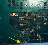
From your photo - note the possibility of excess solder on R2 to make contact with the heatsink. There is adequate clearance designed in for the 3886 chip leads, but R2 is a tight fit.
Thanks for the advice - It doesn't look like R2 should be making contact (there's still some clearance between PCB and heatsink), but to be sure I'll shove some insulating plastic in between there.
I have some Kapton tape that works well in that spot. Not worth buying an entire roll, but maybe you can find something similar to use.
Well, I gave it another try and now none of the boards is acting up like before, but one of them is just much louder than the other one. The more quiet one is the one where I replaced R11, btw. Humming/buzzing disappears when connecting heatsink and PGND to earth ground on both channels. The difference in volume is such that I have to put my head right in front of the quiet channel's speaker to get an approximately balanced sound (the speakers are about 1m apart).
Also, I noticed the channel with lower volume has 14.5/14.3 on the 14V rails where as the louder one has 14.5 on both of them - might this have anything to do with the problem? Neither of the two runs excessively hot. Perhaps they just need another cleaning...
Also, I noticed the channel with lower volume has 14.5/14.3 on the 14V rails where as the louder one has 14.5 on both of them - might this have anything to do with the problem? Neither of the two runs excessively hot. Perhaps they just need another cleaning...
Take a look at the conversation around this post. The LM318 is socket mounted on that V1.3 board, but as suggested I was able to check the strength of the signal with a set of PC earphones with a cap for safety. It would be difficult to do on the surface mount 318 on the FE, but the schematic should guide you to a more accessible nearby location for the test. The signal strength should be the same - See Mark's reply at post #1826
(Dario/Mark, I'm assuming that part of the circuit is consistent across both versions. Correct me if I'm wrong here.)
(Dario/Mark, I'm assuming that part of the circuit is consistent across both versions. Correct me if I'm wrong here.)
Last edited:
Take a look at the conversation around this post. The LM318 is socket mounted on that V1.3 board, but as suggested I was able to check the strength of the signal with a set of PC earphines with a cap for safety. It would be difficult to do on the surface mount 318 on the FE, but the schematic should guide you to a more accessible nearby location for the readings. The signal strength should be the same - See Mark's reply at post #1826
(Dario, I'm assuming that part of the circuit is consistent across both versions. Correct me if I'm wrong here.)
Thanks, I might try that if cleaning the boards doesn't do the trick and I can't find anything else wrong with them. I might also just take everything to university and hook the boards up to an oscilloscope to make things a bit easier. I do think cleaning might help though, since the solder I use seems to have a really bad (as in, conductive) flux core and I've "fixed" a bunch of non-working circuits by simply brushing them down with a good amount of iso (among them my FE, as I mentioned in one of my posts). I'm thinking I may have caused a partial short across the input or something like that.
Thanks, I might try that if cleaning the boards doesn't do the trick and I can't find anything else wrong with them. I might also just take everything to university and hook the boards up to an oscilloscope to make things a bit easier. I do think cleaning might help though, since the solder I use seems to have a really bad (as in, conductive) flux core and I've "fixed" a bunch of non-working circuits by simply brushing them down with a good amount of iso (among them my FE, as I mentioned in one of my posts). I'm thinking I may have caused a partial short across the input or something like that.
Whew! I gave both boards another thorough cleaning and now they're working perfectly! 😎
Even with PGND and the heatsink connected to earth ground, there's still a tiny bit of hum left when I turn the volume up to the maximum, but I tried grounding the shielding of one channel's hook-up cables and that shut it up completely, so I think in the final amp I'll be fine as long as I use shielded cables throughout.
I should also mention that the amp sounds absolutely fabulous!
Last edited:
- Home
- Amplifiers
- Chip Amps
- My_Ref Fremen Edition - Build thread and tutorial