.... the amp sounds excellent - except for the ground loop noise (which is not very loud at listenable music levels, but that's at only about 1/5 of the pot's total travel).......
Do you still have the PGND pad connected to something - chassis or Earth ground?
No, but I tried connecting it to earth ground a few times and it made no difference in sound.Do you still have the PGND pad connected to something - chassis or Earth ground?
Have you tried using a battery powered source (phone or Walkman) as a test? Also, if you read back in the thread several builders had hum problems related to the metal cans of the K caps. Do you have something different to try at C13? I chased a similar problem for months and the cause was an internally defective input RCA socket.
what was the problem?..........I chased a similar problem for months and the cause was an internally defective input RCA socket.
Shorted, or open, or broken and intermittent?
Have you tried using a battery powered source (phone or Walkman) as a test? Also, if you read back in the thread several builders had hum problems related to the metal cans of the K caps. Do you have something different to try at C13? I chased a similar problem for months and the cause was an internally defective input RCA socket.
I just tried attaching my phone directly to the pot, and the buzzing was still there. It's actually a sound with two components - one is 60hz hum, which disappears when I connect signal ground to earth ground, and the other sounds just like a bad ground somewhere in the signal path. I've managed to get it completely silent by grounding the aluminium plate I'm using as a heatsink for testing, so I guess when I finally build my amps I'll just ground the heatsinks and chassis. It's just odd that the aluminium plate should have an effect when there's no galvanic contact with any components. Not that I really care as long as the noise is gone. Now I just have to get the other board working...
Last edited:
what was the problem?
Shorted, or open, or broken and intermittent?
It was actually a combination of things. Either the milling, the insulator or foreign material was allowing what I'll call a "ghost" hum that started as intermittent growing to constant. I didn't see anything when I took it apart, but reassembly was successful. I should add that I also found a broken signal pin inside the plug that needed fixing. That had the same effect as having nothing connected to the input - big noise!
@butizzle - Are you saying something like a 60hz noise is there with the phone??? This all aluminum chassis has a single PE connection - nothing from the board and Antek shield wire not used. Touching the metal has no effect. I have never liked the pin/socket so I soldered the input leads as shown. The socket sleeves can loosen with excessive use. I'll go straight to the board later, but I needed to do this to eliminate one possible source of the hum problem. (note - these are beta boards)
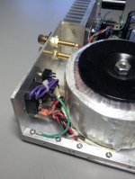
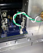
Can you post a photo of how your power leads connect and their proximity to the heat sink?
Attachments
I tried to take a photo where you can see what's going on but everything's so small that it's impossible to make anything out and the fact that I've already desoldered most of the in/out connections again makes it even harder to see, so I'll try to explain my test setup:
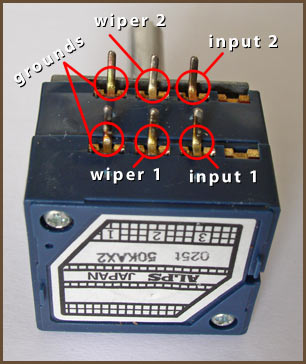
The FE board gets its power from an Antek AS-2225 (I'd actually ordered an AN-2225, and the AS-2225 is not described or mentioned anywhere on the Antek site) the way it's described in the build tutorial on the Google drive and I'm using the original leads with some fast-on plugs attached. I'd guess they're about 40cm in length. The purple shield wire was not used, mainly because I didn't know what it was. The input goes from an RCA connector via a shielded twisted-pair cable - the shield wasn't connected to anything - to an Alps RK27 pot and from there via another shielded cable of the same type to the FE input. The shield of this cable was connected to signal ground at the RK27 ground terminal. I wired the RK27 as shown in the following picture (as found on google - the source is tangentsoft.net, also known for their cmoy tutorial):
As a temporary heatsink, I used an old aluminium front panel. This was not connected to anything in the circuit, as the 3886TF has an all-plastic package. There was no actual chassis, and thus no safety earth (all mains voltage lines were properly isolated of course), no shielding except for the input cable and no star ground point. Just a minimal, bare-bones circuit to test the function of the boards.
In this configuration, there was both a low mains hum - whether I fed a mains-driven preamp or a battery-powered phone into the preamp - and a more harsh, higher-pitched sound that I identify with bad ground connections. This noise varied greatly and by pulling/twisting on the cable, it was possible to eliminate it almost entirely. Both of these noises' volumes were controlled by the potentiometer, which seems odd to me. As I mentioned in my last post, to fix the mains hum permanently, I just needed to hold an earth ground wire to either signal ground or the FE's PGND tab (there's a 1 ohm resistor between the 0V point and GND in the FE - I must admit I'm unsure what it's for). Just touching a ground point in the circuit with my hand also worked to kill the mains hum.
As I wrote above, the other noise was stopped when I touched a spot where the anodization in the aluminium panel had worn through with the other wire connected to earth ground (I have 2 of these coming out of my jury-rigged wall plug - originally to supply two boards with an earth ground connection for PGND, but I was getting waay ahead of myself there). The noise was gone as far as I could hear and the amp seemed dead quiet. I didn't turn the volume up high though so maybe it was just a lot more quiet than before.
Anyway, does anyone have an idea what might be wrong with my other board? I've cleaned it 3 times now and it didn't help. All the resistance (probably doesn't mean much with all those active parts) measurements I did with the board turned off are identical to those on the working board.
Buti,
you have labeled the vol pot in a misleading way. That could result in a wiring layout that causes hum and other interference.
The middle pin is the wiper. This is the Hot Output to the next stage.
The pins labeled input 1 and 2 are the Hot Input from the previous stage.
The third pins are the common inputs/outputs.
The Input Flow/Hot wire goes to Input.
The Input Return/Cold goes to the third pin/common
The Output Flow/Hot comes from the wiper
The Output Return/Cold comes from the third pin/common.
You NEED two input wires for each channel.
You NEED two output wires for each channel.
That makes a total of 8 wires arranged as 4 twisted pairs.
Buti,
you have labeled the vol pot in a misleading way. That could result in a wiring layout that causes hum and other interference.
The middle pin is the wiper. This is the Hot Output to the next stage.
The pins labeled input 1 and 2 are the Hot Input from the previous stage.
The third pins are the common inputs/outputs.
The Input Flow/Hot wire goes to Input.
The Input Return/cold goes to the third pin/common
The Output Flow/Hot comes from the wiper
The Output Return/cold comes from the third pin/common.
You NEED two input wires for each channel.
You NEED two output wires for each channel.
That makes a total of 8 wires arranged as 4 twisted pairs.
I'm aware of that, and I did have 4 wires attached to the pot per channel. I do know how a potentiometer works. The way you described it is exactly how I wired it, and to be honest I can't imagine any other interpretation of the picture I posted. You obviously need 2 wires going to the power amp input and just as obviously 2 wires need to come in from the preamp. Can't transmit a signal on one wire without a reference potential. Is there even a way to wire a pot so it still regulates the volume as expected but doesn't have 4 wires/channel connected?
On a side note, I measured some resistances on that board while searching for possible shorts and came across an oddity: There's a short (or almost - my DMM shows about 1-2 ohms whereas for true shorts it usually shows 0.3-0.6) between the LM3886's pin 3 and the output, even though there's a 47 ohm resistor in between. I also measured this resistance on the "working" board and it's the same there. Is this normal?
If you're referring to LM3886 pin 3 as per datasheet, it's normal, pin 3 is the output.
Or I'm missing something?
Well, after replacing the LM318, the board with a good pair of +-14V rails is now officially working.
Fine 🙂
Also, on the other board I started pulling stuff off, and after replacing T201 and D3 and removing both LM318 and LM3886 I had working 14V rails. I soldered in a new 318 and the rails were still good, but now I installed a new 3886 and one rail has dropped to 6V.
Did you measure the passives before mounting LM318 and LM3886?
I've managed to get it completely silent by grounding the aluminium plate I'm using as a heatsink for testing, so I guess when I finally build my amps I'll just ground the heatsinks and chassis.
Do you have very sensistive loudspeakers?
If so it could be normal, in such case the heatsink should be grounded.
The HSGND pad is there for that reason, to be used in case the heastink is not grounded via the chassis.
Yes,...... I did have 4 wires attached to the pot per channel................. Is there even a way to wire a pot so it still regulates the volume as expected but doesn't have 4 wires/channel connected?
there is another way (at least).
wire Hot from Source to pot.
wire Hot from pot to Amp.
Wire vol pot ground to the mains audio ground/PSU zerovolts/Chassis/Power Ground.
All four of these "ground" options are WRONG. They lead to LOOP AREA in the signal wiring.
You can see this mistake in many of the pics posted on this Forum.
It is a very common error. That gets repeated even though there are many posts telling Members how to do it correctly.
ALL connections between modules are TWO WIRE connections, consisting of a Flow and Return. For least interference these TWO wires must be close coupled throughout their route.
"reference potential" is different.Can't transmit a signal on one wire without a reference potential
A connection is a signal that passes from the SOURCE out to a LOAD and RETURNS to the SOURCE.
A reference potential is a connection that refers two different circuits to the same voltage. No (wanted) Signal passes along the reference wire/trace/Chassis. interference current and noise current can pass along the reference connection and can give rise to a noise voltage between the two circuits. If there is NO shared ROUTE between the Signal Route and the Noise Route then the signal circuits do not "hear" the noise.
Last edited:
An isolated heatsink can be capacitively coupled to the Chassis and/or to the Main Audio Ground.............Do you have very sensistive loudspeakers?
.......... in such case the heatsink should be grounded.
The HSGND pad is there for that reason, to be used in case the heastink is not grounded via the chassis.
The Capacitor presents a low impedance to the noise and interference currents that can circulate, without needing a solid wire connection that goes right down to DC.
Might be worth trying both, to see if either helps solve the problem.
An isolated heatsink can be capacitively coupled to the Chassis and/or to the Main Audio Ground.
The Capacitor presents a low impedance to the noise and interference currents that can circulate, without needing a solid wire connection that goes right down to DC.
Might be worth trying both, to see if either helps solve the problem.
Well, when I build the final amps with chassis and all, the heatsinks will be connected to the chassis anyway (I'll just tap some threads and screw them right on), so they'll automatically be grounded anyway as the chassis will have safety earth connected to it.
Gotcha. I did get a bit confused there - what I meant is that a signal needs some kind of reference to be meaningful. In our case this is the signal ground which defines "0V" for our audio signal. Reference potential was definitely the wrong term."reference potential" is different.
A connection is a signal that passes from the SOURCE out to a LOAD and RETURNS to the SOURCE.
A reference potential is a connection that refers two different circuits to the same voltage. No (wanted) Signal passes along the reference wire/trace/Chassis. interference current and noise current can pass along the reference connection and can give rise to a noise voltage between the two circuits. If there is NO shared ROUTE between the Signal Route and the Noise Route then the signal circuits do not "hear" the noise.
You still have this wrong..................... what I meant is that a signal needs some kind of reference to be meaningful. In our case this is the signal ground which defines "0V" for our audio signal. Reference potential was definitely the wrong term.
Signal requires a two wire connection.
The Flow and the Return come from the Source.
If you build in a loop for that two wire connection you make the connection susceptible to interference.
It is better to make the two wire connection closed coupled.
This is easily achieved with a twisted pair.
What you don't do is run one wire to the receiver terminal and run the other wire to a different part of the amplifier such that you incorporate LOOP AREA.
Last edited:
You still have this wrong.
Signal requires a two wire connection.
The Flow and the Return come from the Source.
If you build in a loop for that two wire connection you make the connection susceptible to interference.
It is better to make the two wire connection closed coupled.
This is easily achieved with a twisted pair.
What you don't do is run one wire to the receiver terminal and run the other wire to a different part of the amplifier such that you incorporate LOOP AREA.
No, I don't. The ground wire representing a 0V reference for the signal does not preclude it from being a return path for the signal current. In case of differential signaling, instead of a 0V line there is a -vin line, but the principle is the same - you need two wires to get a potential difference for the amp to work with. You're thinking in terms of current, but audio amps are voltage amps (at least at the input stage). In a ideal audio amp, you wouldn't even have any current at the input at all since the perfect voltage amplifier has infinite inout resistance.
Anyway, let's put this off-topic discussion aside and focus on the fremen edition amps.
Maybe someone even has an idea what might be wrong with my other channel😉🙂
One process that helped me with a MR V1.3 problem was to print the schematic, lay it on the table next to the non-powered board and simply probe for continuity (and shorts) - not resistance or current. It sounds very basic but helped me discover a resistor that appeared good but had a broken lead near the body (under the shell), and also a cold solder joint hidden under the relay. Have you done that step?
Last edited:
Maybe someone even has an idea what might be wrong with my other channel😉🙂
Did you measure the passives before mounting LM318 and LM3886?
I forgot to post this, had it typed up but got distracted before I could press the submit button... Sorry about that!
Sorry, I didn't write that very clearly. By "output" I meant the actual "OUT" tab on the board - if I'm reading the schematic correctly, R3 should be between pin 3 of the 3886 and that tab?
I'm using a pair of Energy Point 1e's, I don't think these are known to be very sensitive but due to their age I can't find any specs beyond frequency response on the internet... No matter though, I killed the hum and all is well (on that board). 🙂 Thanks again for your help!
If you're referring to LM3886 pin 3 as per datasheet, it's normal, pin 3 is the output.
Or I'm missing something?
Sorry, I didn't write that very clearly. By "output" I meant the actual "OUT" tab on the board - if I'm reading the schematic correctly, R3 should be between pin 3 of the 3886 and that tab?
I'm afraid I let that one slip past me... I was so excited to have working 14V rails that I couldn't wait to get the board up and running. Am I gonna have to remove the amp ICs again (please say no... it took me like 45 minutes to get the solder out of those holes), or do you have a guess as to what might be causing the problem?Did you measure the passives before mounting LM318 and LM3886?
Do you have very sensistive loudspeakers?
If so it could be normal, in such case the heatsink should be grounded.
The HSGND pad is there for that reason, to be used in case the heastink is not grounded via the chassis.
I'm using a pair of Energy Point 1e's, I don't think these are known to be very sensitive but due to their age I can't find any specs beyond frequency response on the internet... No matter though, I killed the hum and all is well (on that board). 🙂 Thanks again for your help!
Sorry, I didn't write that very clearly. By "output" I meant the actual "OUT" tab on the board - if I'm reading the schematic correctly, R3 should be between pin 3 of the 3886 and that tab?
It's correct but it's a very low value resistor, 0.47 Ohm, maybe it's for this reason that you MM see a short.
I'm afraid I let that one slip past me... I was so excited to have working 14V rails that I couldn't wait to get the board up and running.
It's a very important step... if you fried the LM318 one of the reasons could be a wrong part in the wrong position...also some parts could have been damaged.
Am I gonna have to remove the amp ICs again (please say no... it took me like 45 minutes to get the solder out of those holes)
Did you see the Chip Quik video on YouTube?
https://www.youtube.com/watch?v=FTQqjggeklo
It shows how to remove the excess desoldering alloy with ease.
No matter though, I killed the hum and all is well (on that board). 🙂 Thanks again for your help!
You're welcome 🙂
- Home
- Amplifiers
- Chip Amps
- My_Ref Fremen Edition - Build thread and tutorial