Not sure where to get RJH's, there's none on ebay that I can find, maybe mouser has them.
https://www.elfa.se/elfa3~eu_en/elfa/init.do?item=67-194-21&toc=0
https://www.elfa.se/elfa3~eu_en/elfa/init.do?item=67-196-78&toc=0
Hi everyone, I've just finished hooking up my 2 FE boards that I built a while ago, but never tested to opc's The Wire headphone amp (serving as a preamp). The measurements seemed fine, 10-30mV DC offset, so I hooked up my speakers to the two FE boards it and to my delightment, it was perfectly silent. When I tried to play some music however, it stayed that way. I definitely hear one of the relays click when I turn it on, I'll have to see tomorrow whether they actually both click or if one channel has some other problem. I'll also post some measurements and pictures tomorrow, I just figured I'd write this post now in case someone might know a potential easy fix.
Cheers,
George
Cheers,
George
Very helpful, thank you... Also, what else is there to do to ensure the safety of the speaker besides testing for DC offset and AC noise (which I also did)? Sure, I could have looked at some more voltage reference points and that would have told me the same thing I knew after connecting it to the speakers: It doesn't work.But,
insufficient testing before connecting a speaker !
Anyway, I've been experimenting a bit more. One problem was certainly the fact that I'd forgotten to install J1. I've now corrected that and am currently trying to get just one board working. I noticed that the +/- 14.6V points were around +/- 1-3V. I proceeded to clean the board and reflow any solder joints that looked suspicious, with the result that first the +14.6V point showed the correct voltage, and then after another round of cleaning, so did the other one. The relay (which indeed did not click before) clicked as well. This was all done without any inputs connected. The output had nothing but noise on it, and the best thing about it is that afterwards, I connected it to my preamp and after that, the -14.6V point went back to around -2V. I have now disconnected the input again, but the issue remains.
Also, my PGND is connected to mains earth - is that correct?
Does anyone have any idea what might be wrong here?
Last edited:
All the MyRefs will have noise with nothing at the input. The FE can operate (in most situations) without a connection to PGND. The best way for us to help is if you post clear well lit photos - both sides, both boards.
All the MyRefs will have noise with nothing at the input. The FE can operate (in most situations) without a connection to PGND. The best way for us to help is if you post clear well lit photos - both sides, both boards.
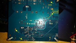
Thanks, I'd already tried disconnecting PGND but it made no difference. Here are the pictures:
First Board:


Symptoms of this board:
-Relay clicks
-2.3V across the -14.6V reference
-0.00V across the +14.6V reference (WTF???)
Second Board:


Symptoms of this board:
-Relay does not click
-14.4V across the +14.6V reference (so this seems to be OK)
-2.3V across the -14.6V reference
Also, all LM317 produce the correct reference voltage of 1.25V across the respective resistors.
I'm pretty stumped. My best guess would be that I somehow fried the op-amps by neglecting to clean up the flux residue, causing a partial short. The flux is now cleaned up, but I guess the damage is done.
Last edited:
I see many places that appear to have very little solder on the pins. Those can easily hide cold joints. It may be due to the lighting/angle, but look through the FE Build Guide for joints with the proper amount of solder. You get high marks for neatness, but you may have been a bit solder stingy at some points.😉
Some places appear to have no solder at all. I'd recommend reheating everything with the aid if a good magnifier.
Some places appear to have no solder at all. I'd recommend reheating everything with the aid if a good magnifier.
Attachments

Last edited:
The output had nothing but noise on it,
An inverting topology Power Amplifier with nothing connected to the input socket is usually noisy.All the MyRefs will have noise with nothing at the input
A non-inverting topology Power Amplifier is usually nearly silent with nothing connected to the input socket.
expect the shorted input noise of <0.1mVac to 2mVac to rise to 2mVac to 10mVac when the input is open.
The FE is non-inverting and when properly wired up should be nearer the <0.1mVac shorted and ~0.2mVac when open input.
This is one of a series of tests you should use to check correct operation.
Last edited:
Thanks for the feedback! I was under the impression that I was more prone to using too much solder, especially on the SMD parts... The only joints where I was less than generous were the fast-on tabs (and one of the big 10mF filter caps has quite the bad connection to ground - that should have no effect on operation though, just make things a bit noisier). Nevertheless, I'll reflow all of the joints again tonight, and if that fails I'll try replacing the LM318s (oh the joy of replacing SMD parts...).I see many places that appear to have very little solder on the pins. Those can easily hide cold joints. It may be due to the lighting/angle, but look through the FE Build Guide for joints with the proper amount of solder. You get high marks for neatness, but you may have been a bit solder stingy at some points.😉
Some places appear to have no solder at all. I'd recommend reheating everything with the aid if a good magnifier.
Edit: just noticed a pad on one of the small signal transistors you pointed out that I actually forgot to solder - thanks a bunch! Gonna correct that tonight and see whether it helps. I sure hope I can get these guys to work!
Also, could the 0V across the 14.6V reference really be a result of my bad soldering? Somehow that just screams short to me...
Last edited:
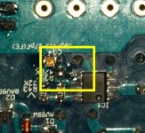
I should have been more specific. The thru-hole parts should be reheated not necessarily the SMD points (if they look good to you). Hopefully you have some liquid or paste flux to apply as you work. Make sure there isn't a solder bridge in this area.
Attachments
Last edited:
Nevertheless, I'll reflow all of the joints again tonight, and if that fails I'll try replacing the LM318s (oh the joy of replacing SMD parts...).
(...)
Also, could the 0V across the 14.6V reference really be a result of my bad soldering? Somehow that just screams short to me...
Unless you have a desoldering hot air gun I suggest you to buy ChipQuik desoldering alloy for safe SMD desoldering.
On the first board one MUR820 looks suspect (it seem burnt).
On both boards SMD joints are too much rich.
BTW I would check first the +-35V points, do you have correct values there?
Also check the correct mounting (orientation) of the zeners on the regulators.
After that I would suggest you to:
First desolder the LM3886, repeat measure.
If values don't change, desolder the LM318, repeat measure.
If values don't change remove T201 and measure D205, if it's not -14V replace both with new parts.
Now measure again, you should have correct values.
Do the same with the positive regulator.
From there double check every joint for bridges to other pins or ground plane.
Measure resistors and caps on PS and signal paths, since there are no active parts mounted you should be able to measure most of them on board.
If all seem right solder a new LM318 and a new LM3886, take care to not use too much solder on SMD parts.
Cross your fingers and power on.
It could be a good idea to use a Dim-bulb Radio Tester for the first power up.
Thanks for the help Dario! The unregulated rails are fine, both polarities on both boards are sitting at 32.2V from ground - I guess that means all the MUR820 diodes are fine. The one looking burned in the first pic looks identical to the others in reality - I have no idea why it looks so weird on the photo. The oversoldered SMD joints shouldn't have an effect on the operation of the amplifier, right? Fixing those would be quite the pain.
Also, I checked the zener orientations (plus all the other diodes) and they are correct, too. I also soldered the pad I'd missed that bcmbob pointed out - it didn't have any effect on the symptoms.
I guess I'll have to desolder the LM3886s tomorrow. I already have a quik chip kit, by the way - unfortunately, this isn't the first time I've screwed up soldering SMD stuff 😉
Would you recommend desoldering the 3886 with the quik chip or is there some easier way? It would use quite a lot of the quik chip solder, which isn't exactly cheap...
Last edited:
A difficult way that destroys the 3886 is to sniip all 11 leads of the 3886, then remove each redundant pin from the PCB.
Yeah, that's what I was trying to avoid... I'm pretty sure my 3886s are still good, since I never even touched the leads and the case is plastic, and it didn't even get hot when I soldered it. The 318s are a different case though - at one point, some sparks and smoke came from one of them, probably because of the crappy flux core solder that I used without cleaning the board before powering it up for the first time... Another lesson learned, I guess. I think I'll start by removing the LM318s and check the +/- 14V rails instead of starting with removing the 3886 as Dario suggested - or is there any compelling reason not to do it in this order?A difficult way that destroys the 3886 is to sniip all 11 leads of the 3886, then remove each redundant pin from the PCB.
Been down this road more times than I'd like to say, but I've had success with both methods. If you try to desolder, the Chip Quick (at least the flux) is a must, IMHO. Even then it takes multiple passes and lots of solder wick. Often it requires using something to push and clear each individual pin in sequence. I even apply a lot of flux to the braid - neither are cheap and can end up costing more than the LM3886.
It's a fun challenge to complete, but if shipping to Switzerland is reasonable $7 USD ea. can be well worth the time and cost of supplies saved by using the clip and pull method.
It's a fun challenge to complete, but if shipping to Switzerland is reasonable $7 USD ea. can be well worth the time and cost of supplies saved by using the clip and pull method.
Alright, I went ahead and desoldered the LM318s. One board now gives +/-14.4V and seems to be fine - I guess the culprit really was the LM318 there. The other board however is still acting up: It's putting out around +1.94 and -5.1V. Could the LM3886 be causing this, or is there still hope that I won't have to try and remove it?
On a side note, I measured some resistances on that board while searching for possible shorts and came across an oddity: There's a short (or almost - my DMM shows about 1-2 ohms whereas for true shorts it usually shows 0.3-0.6) between the LM3886's pin 3 and the output, even though there's a 47 ohm resistor in between. I also measured this resistance on the "working" board and it's the same there. Is this normal?
I'd also like to extend my thanks to everyone who has helped me in this thread - I don't know what I'd do without people like you! Nearly every DIY electronics project I've ever built didn't work right off the bat, and I could always count on awesome people in forums like this one to help me out. Thanks again!
Last edited:
Well, after replacing the LM318, the board with a good pair of +-14V rails is now officially working. I'm gonna remove the 3886 from the other one and see if that has any effect on the 14V rails.
I'm also having a very strange issue with the working board: I get a noise that sounds like a bad ground connection/ground loop and that behaves very strangely. Its volume follows the potentiometer position (which would indicate a problem at the pot or the preamp, no?), but it also gets louder if I touch anything that's connected to the amplifier - for example, the (isolated, obviously) cable I'm using for the input, the input cap (I'm using the Soviet K71 caps) or even the wooden table the amp is sitting on. Touching the connection of the signal ground wire to the board (I've tried both soldering the cables to the little pins and to the back side - makes no difference) also changes the intensity of the noise - when I find the right spot/angle to press it'll disappear almost completely, but it can also get a lot louder.
The cable I'm using is a two-conductor shielded version, but the shielding is not connected to anything right now - might this be the problem?
Is the twisted pair input cable connected at BOTH ends?The cable I'm using is a two-conductor shielded version,
Have you accidentally swapped the +IN and -IN input connections?
Is the +IN at the far end of the input cable OPEN?
Unfortunately, none of those are the case - I was playing music through the amp, and I triple-checked polarity. Everything is fine - the amp sounds excellent - except for the ground loop noise (which is not very loud at listenable music levels, but that's at only about 1/5 of the pot's total travel).Is the twisted pair input cable connected at BOTH ends?
Have you accidentally swapped the +IN and -IN input connections?
Is the +IN at the far end of the input cable OPEN?
Also, on the other board I started pulling stuff off, and after replacing T201 and D3 and removing both LM318 and LM3886 I had working 14V rails. I soldered in a new 318 and the rails were still good, but now I installed a new 3886 and one rail has dropped to 6V. I'm not sure if I didn't clean the board well enough or something, but I do know that I didn't fry the LM3886 - I only soldered each lead for about half a second at a time and waited for it to cool afterwards before doing the next lead, and the chip never got more than lukewarm. The relay doesn't click when the amp turns on (as you'd expect), but it does cycle once when powering down, about 3-6s after pulling the plug.
Last edited:
- Home
- Amplifiers
- Chip Amps
- My_Ref Fremen Edition - Build thread and tutorial