Dario, i was measuring 35 v between lm317 legs. If I measure it between leg of cap and lm317 it shows 35 v on good side and something like 70 vdc on shorted.
Ok, so on 'shorted' board you'll have to replace LM317, possibly transistor,zener and LM318.
On C102/C202 what voltages do you measure?
The 'good' board measure like my pic? If so it's fine and you can try it.
Use a toothpick!
LOVE the toothpick idea!
Ivan,
Stick with it. It may not feel like it, but you are getting there. All of us have been where you are a sometime. Everybody on the thread is behind you. I just wish I could offer more help on the diagnostics.
Jac
Sorry
102 value is 14.1
202 value is 3.6 and swinging (initially it is 7 or so, but keeps dropping till 3 or maybe lower- I did not wait that long)
Where? On C102/C202?
Ivan, please, be more precise 😉
102 value is 14.1
202 value is 3.6 and swinging (initially it is 7 or so, but keeps dropping till 3 or maybe lower- I did not wait that long)
Last edited:
I have checked good board- values are fine ...
Fine, so if that board has a low DC offset you can use it.
102 value is 14.1
202 value is 3.6 and swinging
Ok, for sure LM317 have to replaced and probably also the BC640-16 and zener.
I would buy also a LM318 just to be sure you have it at hand.
Good I have day off today.
Not sure about you guys 🙂
So yesterday boards were fine and if only I would not use cheap mmeter to confirm fluke's values I d be fine...
Cheap and slippery 🙁
Not sure about you guys 🙂
So yesterday boards were fine and if only I would not use cheap mmeter to confirm fluke's values I d be fine...
Cheap and slippery 🙁
Thank you !
I ll order parts . Probably it has to be ebay or something with low delivery costs .. does anybody know a good source apart mouser ? 🙂
Dario, it would be handy to add measurement tips of how to do it properly in build manual to avoid problems with guys like I am 😀
I ll order parts . Probably it has to be ebay or something with low delivery costs .. does anybody know a good source apart mouser ? 🙂
Dario, it would be handy to add measurement tips of how to do it properly in build manual to avoid problems with guys like I am 😀
Thank you !
I ll order parts . Probably it has to be ebay or something with low delivery costs .. does anybody know a good source apart mouser ? 🙂
uk.farnell.com
Geoff
Just fired up the amps. First try was through dim tester with 60 W bulb. The light became dim after a mild flash. When amps were plugged directly into the wall socket outputs showed 2.8 and 4 mV DC. Now keeping fingers crossed for Ivan to overcome the problems and succeed with the build! Hope to report sound impressions soon.
Attachments
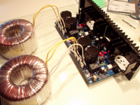
twisted pairs everywhere !Just fired up the amps. First try was through dim tester with 60 W bulb. The light became dim after a mild flash. When amps were plugged directly into the wall socket outputs showed 2.8 and 4 mV DC. Now keeping fingers crossed for Ivan to overcome the problems and succeed with the build! Hope to report sound impressions soon.
When amps were plugged directly into the wall socket outputs showed 2.8 and 4 mV DC. (...)Hope to report sound impressions soon.
Really good values 🙂
Good work.
Keep us informed (and twist secondarily wires... ;-) )
Sent from my LT22i using Tapatalk 4 Beta
Thank you! Secondaries will be twisted.twisted pairs everywhere !
Ivan I don't have any of the BC transistors but do have some BD139-16/BD140-16 which Dario says are an equivalent.If they are of any use I can post some to you.
Ok Ivan good luck with this you will like the sound.If things go well I'll be testing mine in the next couple of days.I've got my fingers crossed.
- Home
- Amplifiers
- Chip Amps
- My_Ref Fremen Edition - Build thread and tutorial