Gents, is there any specific requirements for placement of off board parts ?
I assume you are referring to C13. Bob has graciously offered to let me borrow some caps to try a few different orientations. I will go into these in more detail when the caps arrive and I get them in place. Stay tuned. I will say though Dario has not had any issues with the way he has mounted the caps offboard, so following his suggestion should work.
Last edited:
Another successful build
For those that have yet to start their build:
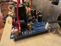
This is my 5th Fremen Edition successfull build, no hum, not a single problem, working and singing from first power on.
DC offset is 25mV with open input, as usual it will lower between 5-10mV after the first tens of hours of use.
So be confident. 🙂


As you can see, since this build will have off board caps, I've shorted C13 position, so boards are DC coupled.
I will report any problem or suggestion as I procced with this build.
For those that have yet to start their build:
This is my 5th Fremen Edition successfull build, no hum, not a single problem, working and singing from first power on.
DC offset is 25mV with open input, as usual it will lower between 5-10mV after the first tens of hours of use.
So be confident. 🙂
Gents, is there any specific requirements for placement of off board parts ?
As you can see, since this build will have off board caps, I've shorted C13 position, so boards are DC coupled.
I will report any problem or suggestion as I procced with this build.
Attachments

Thx Dario
I need to understand general practice of fitting big passive elements.
1. Is jumper mandatory then doing so ?
2. Is caps being connected from two furthermost apart dedicated pcb holes or there is another method I do not understand ?
I need to understand general practice of fitting big passive elements.
1. Is jumper mandatory then doing so ?
2. Is caps being connected from two furthermost apart dedicated pcb holes or there is another method I do not understand ?
1. Is jumper mandatory then doing so ?
No, simply a design choice.
You can do differently if you think it's better.
2. Is caps being connected from two furthermost apart dedicated pcb holes or there is another method I do not understand ?
The amp module become DC coupled. The input cap will be between the RCA connector and the molex connector on board.
RCA->cable -> input cap -> cable -> molex -> PCB
In the above explanation of mounting the cap off the pcb how are you orienting the wiring for the cap and ground?
how are you orienting the wiring for the cap and ground?
Sorry I can't understand... can you elaborate a bit?
Sure, sorry. Are you running the signal ground along side of the input cap, separate, twisted around it, etc. How are you connecting the cap to the wire? Are you just soldering the leads to wire, or are you using some kind of connectors? Thanks
Sure, sorry. Are you running the signal ground along side of the input cap, separate, twisted around it, etc. How are you connecting the cap to the wire? Are you just soldering the leads to wire, or are you using some kind of connectors? Thanks
I've tested modules DC coupled with my actual cabling, I've yet to realize cabling (which includes coupling cap).
My intention (setup includes a TKD 2CP-2511 volume pot) is to solder caps directly on pot outputs and on hot of the balanced cable I'll use, the ground of the balanced cable will go directly to pot also.
So there will be input RCAs, balanced cable to pot input, caps on pot output, balanced cable to molex plug which will be branched to the molex connector on PCBs.
I hope it's clear, btw when I'll realize it and I'll post pics it will be clear... 😉
Got it. Sounds like a great idea. The inputs caps being in a separate passive pre could make swapping even easier.
For most music system AC coupling is safer for speaker.
The DC blocking capacitor between the Source and the Power Amplifier can be located at the Source Output or at the Receiver Input.
The DC only needs to be blocked once between any two components.
The DC blocking capacitor between the Source and the Power Amplifier can be located at the Source Output or at the Receiver Input.
The DC only needs to be blocked once between any two components.
Thanks,I'm not an expert (the DC protection circuit has been designed by Penasa) but I expect it to work also with the -16 version.
I confirm my DC protection circuit works with the -16.
Guys, which switches do you suggest to use for amp ?
I am looking for push button on off switch for amp and one toggling for source selection on on . From mouser ..
Thx
I am looking for push button on off switch for amp and one toggling for source selection on on . From mouser ..
Thx
Guys, which switches do you suggest to use for amp ?
I am looking for push button on off switch for amp and one toggling for source selection on on . From mouser ..
Thx
What do you want them to look like?
Tbh just looking for a creative idea. On off is just momentary push button and source switch can be Anything
For the power switch are you using a switch driver and a relay? If you are a momentary will work if not you need a switch that latches. I used a schurter pushbutton dpst on my integrated, its nice but there is switch bounce if im not careful. I used a bulgin switch for the fe that is lighted and the amb driver/ relay setup....cool little project and really nice compared to the bare switch. Allied had some of the switches on sale a while back.
That is interesting. Thank you, Will.
Do you think 2 source selection is ok to do with mechanical switch or something like relay based is Better?
Do you think 2 source selection is ok to do with mechanical switch or something like relay based is Better?
A relay based source election would be really cool, but I don't known of a board or kit available (someone else may have some input here). But I am pretty sure schurter makes a latching on/ on pushbutton that would be simple.
A relay based source election would be really cool, but I don't known of a board or kit available (someone else may have some input here).
Maybe not exactly what you're searching... but..
Mezmerize B1 Buffer Preamp (Makes 2 channels; Rev 1.0) - PCBs
A relay based source election would be really cool, but I don't known of a board or kit available (someone else may have some input here). But I am pretty sure schurter makes a latching on/ on pushbutton that would be simple.
Perhaps you find one of these input selectors usefull:
Dantimax (elektronik) - Selectors_-_attenuators
Thx for advice guys
I am looking for passive selector with no sound degradation. Ultimate one would be uriah's optical s/selector. But probably would opt for something like shown on amb website.
P.S. I use my b1 as a testing platform , not scared of ruining it. Was planning to do mesmerize but instead I am removing b1 (or analogue) altogether. Lighter note is due to be installed into FE. Buffer stage is going to be JG Buffer for Subbu dac.
And dantimax server is down 😀
- Home
- Amplifiers
- Chip Amps
- My_Ref Fremen Edition - Build thread and tutorial