I'd like to run both boards off of a single transformer- it's an Antek 22V 300A model. What is the best way to do that? The boards each have four connections AC 1,2 and NAC 1,2- how should I handle the wiring?
First of all, Mauro recommended individual trafo's for each channel. He mentioned that there was risk of hum with a single transformer powering both channels.
That said, I did the experiment several years ago and measured hum was not significant. Alas, it was so long ago, I can't remember how I hooked up the secondaries. As you know, the two diode bridges on the FE supply the plus and minus voltages separately. That means you must supply AC to both sides.
As for how you connect the secondaries, you have two choices. If you connect the positive AC for both channels from one secondary and both NAC to the other secondary, then you have kept the separation of the polarities but lost independence of the two channels. If you use one secondary for each channel and parallel the AC and NAC connections, you have a different noise risk.
Honestly, I would try both ways once you get it running, so see if you can measure or hear any difference in noise.
Jac
What is the best way to do that? The boards each have four connections AC 1,2 and NAC 1,2- how should I handle the wiring? Would jumpers work connecting AC 1&2? Or should I split each of the AC wires into 2 at the transformer and make all four connections with each board?
Given two wires of a secondary, one goes to ACn, the other to NACn.
Follow directions in the build guide...
Last edited:
Hi,
after years of flawless work I decided to add a LDR volume control to my My_Ref FE v 1.02
When I turned on the amp for the first time after the installation of the new stuff everything seemed to work correctly.
After ten minutes of good music I turned off the amp then I turned it on again, but one of the channels did not turn on. No led, no click from the relay.
So I turned off the main switch of the amp and here I got a surprise... after some seconds the led of the 'broken' channel turned on for a second and I heard the click from the realy...
Trying to understand what was goin'on I disconnected the board from everything except the power supply, turned on and off the amp with the same behavior.
I exchanged the power supply of the two boards with the same result: after some seconds i've turned off the amp le led lights on for a second and the relay clicks.
Then I disconnected the power supply from the board too and left the amp quiet for a while.
After one hour I connected the power supply to the board and turned on the amp.
The Led lighted on and the relay clicked!
Turned off the amp and turned on again...
The Led lighted on and the relay clicked! Great!
Turned off the amp and turned on again...
...the problem again.. no led light, no relay clicks...
So now I need some advice about how to go ahead with the diagnostic...
Thank you in advance for your patience...
Filippo
Hi Fillipo,
I would start by tracing voltages through the switch, transformer, and output of the power supply (in particular the top of C14 that is the power to the relay). Even better would be to measure the voltage just before the relay at the top of R21 and R22. That should be about 24VDC. You can also measure the V+ and V- and the across the speaker outputs for DC.
The best would be to compare voltage measurements when it works and when it isn't working. At the moment, I don't find enough information to figure out what part of the system isn't working. If everything is good everytime up to C14, then it's likely in the turn-on delay/DC offset part of the board where the relay lives.
I've had similar behavior from a relay that got tired. If you trace all the voltages and don't find any other problem, I would probably change the relay first, just because it's a mechanical part that can wear out.
Good luck.
Jac
Ciao Filippo,
download the build guide I've linked some posts ago, at chapter 10 you'll find some voltages to measure.
Do it and post results.
It's unlikely that the problem lies in the DC protection circuit, something is broken in the amp part, probably the LM318 or something in the regulator.
download the build guide I've linked some posts ago, at chapter 10 you'll find some voltages to measure.
Do it and post results.
It's unlikely that the problem lies in the DC protection circuit, something is broken in the amp part, probably the LM318 or something in the regulator.
Hi Dario and Jac
first of all thank you for the quick reply.
Done the measurements according to chapter 10 of the build guide.
I've found that the voltage across D205 and c202 is 0 (zero) where should be -14v and -14.6v
What do you think? Is the zener gone?
Best regards.
Filippo
first of all thank you for the quick reply.
Done the measurements according to chapter 10 of the build guide.
I've found that the voltage across D205 and c202 is 0 (zero) where should be -14v and -14.6v
What do you think? Is the zener gone?
Best regards.
Filippo
first of all thank you for the quick reply.
You're welcome 🙂
Done the measurements according to chapter 10 of the build guide.
I've found that the voltage across D205 and c202 is 0 (zero) where should be -14v and -14.6v
What do you think? Is the zener gone?
The Zener or the LM317.
I would order both and also some BD139-19 and BD140-16 to replace all transistors (so that they're all the same), unless you have some BC640-16 around.
Just a question for Dario:
if i would like to build a 4 Lithium batteries operated My_ref, i should replace rectifiers (not regulators, to obtain a stable voltage) with a direct connection. What DC voltage should enter the boards? 34V?
More: would 5.000 mah (really available) per battery be enough to ensure a 10 hours play time?
And what discharge rate would be needed to ensure no dynamic/sound quality loss? Would 2000 mah be enough?
You would need 18off 3.7Vdc batteries to get a dual ~34Vdc supply.
The average current draw of a 50W chipamp used in a domestic situation would probably be around 100mA.
For ten hours use I'd expect a 1Ahr battery to last that long but be fully depleted and risk damage. Maybe allow 50% extra capacity AND include a low voltage alarm and a very low voltage latching cut off.
I arrived at 100mA by considering 70mA as the quiescent draw and thus 30mA as the output draw after allowing for an efficiency factor.
34V+34V @ (100-70) = ~2W and assuming an effective efficiency of 30% gives a single channel output of 0.6W
You would need 18off 3.7Vdc batteries to get a dual ~34Vdc supply.
The average current draw of a 50W chipamp used in a domestic situation would probably be around 100mA.
For ten hours use I'd expect a 1Ahr battery to last that long but be fully depleted and risk damage. Maybe allow 50% extra capacity AND include a low voltage alarm and a very low voltage latching cut off.
I arrived at 100mA by considering 70mA as the quiescent draw and thus 30mA as the output draw after allowing for an efficiency factor.
34V+34V @ (100-70) = ~2W and assuming an effective efficiency of 30% gives a single channel output of 0.6W
Hello Andrew,
i would use 4 custom-made battery packs, including BMS, so no worries about overdischarging. I was thinking about 4x5000 mah as i know half of the batteries power will be practically unavailable.
I can easily ask for a 1A (or more) discharge rate, using last generation Lithium batteries, so i have a large margin to ensure no SQ loss.
My only remaining doubt is about voltage: batteries output voltage is not stable in time, so i was thinking about exceeding the required voltage then regulating it (i did so in a tube output DAC and the resuts are stunning). So i have to understand if every My-ref power line is regulated onboard and what DC voltage has to be the supplied removing diodes. If even a single power line is not regulated onboard, i have to implement an offboard regulation and i need to know the EXACT voltage to supply...
My only remaining doubt is about voltage: batteries output voltage is not stable in time, so i was thinking about exceeding the required voltage then regulating it (i did so in a tube output DAC and the resuts are stunning). So i have to understand if every My-ref power line is regulated onboard and what DC voltage has to be the supplied removing diodes. If even a single power line is not regulated onboard, i have to implement an offboard regulation and i need to know the EXACT voltage to supply...
Hi Luca,
The input stage (LM318) of My_Ref amps is regulated, but the 2nd stage (LM3886) is not regulated. Also, the speaker protection circuit has a simple +24 VDC power supply that is separate from the input diodes.
Technically, using symmetric power rails, the LM3886 has a max voltage rails of +/- 40 VDC per the datatsheet. The recommended transformers for My_Ref are 24 VAC for 8 ohm speakers and 22 VAC for 4 ohms. That gives about 33 VDC for 8 ohms and about 30 VDC for 4 ohms at no load. So for the rails, a regulated +/- 33 VDC would be fine.
The circuit protection circuit is pretty simple with a turn-on delay and a relay that cuts out the speaker circuit if too much DC is present. I'm sure the component values could be tweaked to work at a different input voltage.
I hope that helps.
Jac
Thank you, very appreciated infos.
It seems to me speaker protection circuit power supply only has rectifiers (half wave), a resistor and a cap for each channel, am i right?
So supplying 24VAC will result in 24VDC, supplying 22VAC will give 22VDC to speaker circuit and so on?
Then i could simply supply 24VDC to C14 (removing DR1 and DR2) and that should be ok, right? If current absorption is very low, i can get 24VDC from a 37V battery via external regulators...
For all the other lines, 37V batteries should be ok, when properly regulated offboard.
Just a question for Dario:
if i would like to build a 4 Lithium batteries operated My_ref, i should replace rectifiers (not regulators, to obtain a stable voltage) with a direct connection. What DC voltage should enter the boards? 34V?
More: would 5.000 mah (really available) per battery be enough to ensure a 10 hours play time?
And what discharge rate would be needed to ensure no dynamic/sound quality loss? Would 2000 mah be enough?
You already received a good amount of qualified answers and BTW I've no experience with batteries supply, so... 😉
Let us know if it makes any difference but, maybe, an intermediate stage would be advisable, like a regulated supply.
I've had reports in the past of a performance increase using a LT1083 regulated supply.
Thank you, very appreciated infos.
It seems to me speaker protection circuit power supply only has rectifiers (half wave), a resistor and a cap for each channel, am i right?
So supplying 24VAC will result in 24VDC, supplying 22VAC will give 22VDC to speaker circuit and so on?
If current absorption is very low, i can get 24VDC from a 37V battery via external regulators...
You have it right. I haven't figured out how much current is used by the speaker protection circuit, but it is not too big. The transistor circuit is a few mA. The LED the same. The biggest current draw is the relay.
Jac

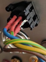
Finally starting on finishing the build
Impressive 🙂
Other pics, please 😉
A higher voltage relay draws less current than a lower voltage relay.You have it right. I haven't figured out how much current is used by the speaker protection circuit, but it is not too big. The transistor circuit is a few mA. The LED the same. The biggest current draw is the relay.
Jac
Choose a 24V, or higher, relay.
If you have more voltage available, then also look at using some form of relay current saver. You can operate a relay reliably at 60% to 70% of it's rated current. But you need to give it a current pulse to ensure absolutely reliable triggering.
Instead of using a 140mW 12V relay operating at ~11.7mA, you can use a 140mW 24V relay operating at ~3.8mA
That's a big saving if using a battery supply.
Don't even think about using 5V relays, nor half watt relays.
Investigate using Solid State relays using ultralow Rdson mosFETs.
Last edited:


- Home
- Amplifiers
- Chip Amps
- My_Ref Fremen Edition - Build thread and tutorial