Hi Dario,
I still have the revision V1.02 - March 2013, which BOM version should I use for the build.
Thanks
I still have the revision V1.02 - March 2013, which BOM version should I use for the build.
Thanks
All of the BOMs on Dario's google drive are labeled by a range of revisions to which they're applicable. [emoji106]
Sent from my iPhone using Tapatalk
Sent from my iPhone using Tapatalk
You would have to convert the whole circuit to a single supply version.
That would be complicated and made more so by having to modify the PCB.
Better to start with a single supply version and design a PCB to suit.
That would be complicated and made more so by having to modify the PCB.
Better to start with a single supply version and design a PCB to suit.
Hi all,
Is any way to use a single secondary tranformer to supply one board?
Thanks
No, you will need a double secondary transformer.
If you have two transformers with single secondaries you can use them.
Hi
I'm wondering if anyone is using (or has tried) the My_Ref Fremen amp on any high-end speakers maybe in the $20,000 to $50,000 range?
If so, how did it sound compared to the (presumably) high-end amp it replaced? 😀😎
bcmbob did a comparison like that several years ago. As I remember, he too his FE to a friend's house and compared it in the friend's system to an expensive tube amp. Bob could tell you what he found.
Yes, thanks; I found it and read it last night - it was comparing the My Ref to a Cary Audio Design CAD-300SEI here: http://www.diyaudio.com/forums/chip-amps/207390-my_ref-fremen-edition-beta-build-fine-tuning-27.html#post3096391.
Also Madisonears wrote one here:http://www.diyaudio.com/forums/chip-amps/216915-my_ref-fremen-edition-rc-build-thread-25.html#post3912591 where he used it in his own high-end system.
Both good reviews and the My Ref was not disgraced!
Also Madisonears wrote one here:http://www.diyaudio.com/forums/chip-amps/216915-my_ref-fremen-edition-rc-build-thread-25.html#post3912591 where he used it in his own high-end system.
Both good reviews and the My Ref was not disgraced!
bcmbob did a comparison like that several years ago. As I remember, he too his FE to a friend's house and compared it in the friend's system to an expensive tube amp. Bob could tell you what he found.
Dario,
is it possible to use a transformer with dual voltage "combined" like 18v-0-18v (3 wires) ?
I have 2 of them both are 250Va and it would be nice to use them for this project.
is it possible to use a transformer with dual voltage "combined" like 18v-0-18v (3 wires) ?
I have 2 of them both are 250Va and it would be nice to use them for this project.
Fremen MP4
I am finally finishing up a project that I started a few years ago using FE 1.02 boards. You know how it goes, life gets in the way of projects.
http://www.diyaudio.com/forums/attachment.php?attachmentid=602194&stc=1&d=1488384981
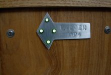
I named the amp for this project “Fremen MP4”. Fremen is in honor of Dario who has kept the My_Ref moving forward all these years. MP is for Mauro Penasa, the original designer of the My_Ref and 4 is for four channels.
http://www.diyaudio.com/forums/attachment.php?attachmentid=602198&stc=1&d=1488384981
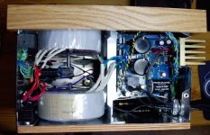
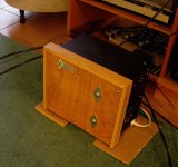
I have tried to make the amplifier case look a bit different and a bit homemade. I'm not sure what an amplifier would look like on planet Arrakis, but I'm pretty sure it wouldn't be the usual aluminum box. Also, I wanted this amp to sit on a bookshelf and bookshelves are not very deep. So the front and back are made of finished plywood, the amp is tightly packed, and everything is stacked vertically.
http://www.diyaudio.com/forums/attachment.php?attachmentid=602196&stc=1&d=1488384981
This amp was built to power Linkwitz LXmini speakers. For those not familiar with Siegfried Linkwitz, his is a scientist whose hobby has been speakers and crossover networks for about 40 years. I know it's that long because I've been reading his articles for more than 30 years. You are probably familiar with Linkwitz-Riley filters (yes, that Linkwitz). Linkwitz is interested in psycho-acoustics, room acoustics, and how to make loudspeakers disappear. If you haven't visited yet, an online trip to Linkwitz Lab is an interesting experience.
Regarding the LXmini, they are two way speakers that use DSP for crossover, equalization, and time coherence. Since the crossover is digital, each driver needs it's own amp. In the case of the Fremen MP4, 4 drivers means four FE boards, 4 transformers, the DSP unit, and a clean power supply for the DSP(a Salas shunt regulator). And it's here that the plywood comes in handy because hanging over 7 kg of transformer per side would buckle many aluminum cases.
http://www.diyaudio.com/forums/attachment.php?attachmentid=602193&stc=1&d=1488384981
The thing to say about the appearance of the LXmini speaker is that it is different. As for me, I care about how it sounds, not how it looks.
Component selection won't be of much interest to you guys who are building the newer boards, but I will share a couple of thoughts on things not to do in building an amp.
http://www.diyaudio.com/forums/attachment.php?attachmentid=602195&stc=1&d=1488384981
Don't build vertically and compactly like I did. There just isn't enough room in there for fingers, so I ended up taking the thing apart everytime I need to change something. As you can see, I stacked the FE boards on one end of the case with all four attached to the same heat sink.
I had this idea of getting rid of the speaker binding posts/internal hookup wire and run the speaker wire directly to the amplifier board. At the same time, I decided I would try the John Risch speaker cables which are “rather stiff”. Combining these two ideas was not a good idea. I had a difficult enough time building this thing without snaking stiff speaker wires through the case and to each board.
My advise to you is build your amp in a nice shallow box with lots of floor space so you can spread things out and reach each of them easily.
http://www.diyaudio.com/forums/attachment.php?attachmentid=602199&stc=1&d=1488384981
As for component selection, having an active crossover let me make choices that might not have been a good idea in a full range amplifier. For example, the high frequency speaker is a 4” Seas full range design that covers 700 – 20k Hz. That means I could choose components that are best at upper mid-range and higher frequencies. For these boards, I used a BG NX at C9 and a first generation Rike S-Cap at C13. Finally, I used a surface mount version of Z-foil from Texas Components at R12. All of these choices work well for clarity, detail, and dynamics.
http://www.diyaudio.com/forums/attachment.php?attachmentid=602197&stc=1&d=1488384981
On the woofer boards, I got use one of my favorite mid-range combinations for C13 with a 1.0 uF Russian K75-10 bypassed by 1 nF Amtrans (see the little black cap peaking out from below the big green cap). At C9, I used a BG PK cap which, combined with the K75-10/Amtrans, gives a very nice mid-range and bass. You could use this combo in a full range amp and it would produce nice warm and liquid music, but you would give up a little detail and clarity on top.
The result is an amp with silent background and very nice sound.
In case you are wondering, yes, the LXmini's sound very nice. Easily equal to my earlier FE amp playing through my DIY speakers based on Dynaudio drivers. The idea of the speakers disappearing is also there, depending on room placement and source material. This combination presents the best image depth I have heard. It's kind of weird because sometimes you can be looking directly at the speakers and your mind is telling you the sound is coming from the stage, not the speaker.
I am finally finishing up a project that I started a few years ago using FE 1.02 boards. You know how it goes, life gets in the way of projects.
http://www.diyaudio.com/forums/attachment.php?attachmentid=602194&stc=1&d=1488384981
I named the amp for this project “Fremen MP4”. Fremen is in honor of Dario who has kept the My_Ref moving forward all these years. MP is for Mauro Penasa, the original designer of the My_Ref and 4 is for four channels.
http://www.diyaudio.com/forums/attachment.php?attachmentid=602198&stc=1&d=1488384981
I have tried to make the amplifier case look a bit different and a bit homemade. I'm not sure what an amplifier would look like on planet Arrakis, but I'm pretty sure it wouldn't be the usual aluminum box. Also, I wanted this amp to sit on a bookshelf and bookshelves are not very deep. So the front and back are made of finished plywood, the amp is tightly packed, and everything is stacked vertically.
http://www.diyaudio.com/forums/attachment.php?attachmentid=602196&stc=1&d=1488384981
This amp was built to power Linkwitz LXmini speakers. For those not familiar with Siegfried Linkwitz, his is a scientist whose hobby has been speakers and crossover networks for about 40 years. I know it's that long because I've been reading his articles for more than 30 years. You are probably familiar with Linkwitz-Riley filters (yes, that Linkwitz). Linkwitz is interested in psycho-acoustics, room acoustics, and how to make loudspeakers disappear. If you haven't visited yet, an online trip to Linkwitz Lab is an interesting experience.
Regarding the LXmini, they are two way speakers that use DSP for crossover, equalization, and time coherence. Since the crossover is digital, each driver needs it's own amp. In the case of the Fremen MP4, 4 drivers means four FE boards, 4 transformers, the DSP unit, and a clean power supply for the DSP(a Salas shunt regulator). And it's here that the plywood comes in handy because hanging over 7 kg of transformer per side would buckle many aluminum cases.
http://www.diyaudio.com/forums/attachment.php?attachmentid=602193&stc=1&d=1488384981
The thing to say about the appearance of the LXmini speaker is that it is different. As for me, I care about how it sounds, not how it looks.
Component selection won't be of much interest to you guys who are building the newer boards, but I will share a couple of thoughts on things not to do in building an amp.
http://www.diyaudio.com/forums/attachment.php?attachmentid=602195&stc=1&d=1488384981
Don't build vertically and compactly like I did. There just isn't enough room in there for fingers, so I ended up taking the thing apart everytime I need to change something. As you can see, I stacked the FE boards on one end of the case with all four attached to the same heat sink.
I had this idea of getting rid of the speaker binding posts/internal hookup wire and run the speaker wire directly to the amplifier board. At the same time, I decided I would try the John Risch speaker cables which are “rather stiff”. Combining these two ideas was not a good idea. I had a difficult enough time building this thing without snaking stiff speaker wires through the case and to each board.
My advise to you is build your amp in a nice shallow box with lots of floor space so you can spread things out and reach each of them easily.
http://www.diyaudio.com/forums/attachment.php?attachmentid=602199&stc=1&d=1488384981
As for component selection, having an active crossover let me make choices that might not have been a good idea in a full range amplifier. For example, the high frequency speaker is a 4” Seas full range design that covers 700 – 20k Hz. That means I could choose components that are best at upper mid-range and higher frequencies. For these boards, I used a BG NX at C9 and a first generation Rike S-Cap at C13. Finally, I used a surface mount version of Z-foil from Texas Components at R12. All of these choices work well for clarity, detail, and dynamics.
http://www.diyaudio.com/forums/attachment.php?attachmentid=602197&stc=1&d=1488384981
On the woofer boards, I got use one of my favorite mid-range combinations for C13 with a 1.0 uF Russian K75-10 bypassed by 1 nF Amtrans (see the little black cap peaking out from below the big green cap). At C9, I used a BG PK cap which, combined with the K75-10/Amtrans, gives a very nice mid-range and bass. You could use this combo in a full range amp and it would produce nice warm and liquid music, but you would give up a little detail and clarity on top.
The result is an amp with silent background and very nice sound.
In case you are wondering, yes, the LXmini's sound very nice. Easily equal to my earlier FE amp playing through my DIY speakers based on Dynaudio drivers. The idea of the speakers disappearing is also there, depending on room placement and source material. This combination presents the best image depth I have heard. It's kind of weird because sometimes you can be looking directly at the speakers and your mind is telling you the sound is coming from the stage, not the speaker.
Attachments
-
 LXmini speaker B.jpeg81.2 KB · Views: 396
 -
 Fremen Tag B.jpeg93 KB · Views: 384
 -
 Fremen MP4 inside B2.jpeg125.1 KB · Views: 395
 -
 Fremen MP4 inside A2.jpeg133.6 KB · Views: 385
 -
 FE LXmini Woofer B.jpeg153.7 KB · Views: 384
 -
 FE LXmini outside B.jpeg154.5 KB · Views: 226
 -
 FE LXmini full range.jpeg147.8 KB · Views: 223
Thanks Dario. I really appreciate all you have done on this amp.
But Koldby, you are clearly a person of taste and style. I like them too, but not everyone thinks plumbing belongs in the living room.
Jac
I, personally, love the look of your speakers!
But Koldby, you are clearly a person of taste and style. I like them too, but not everyone thinks plumbing belongs in the living room.
Jac
For the HF speaker amp, how did you finally choose the Rike S-Cap at C13 - did you try many different caps at C13 and settled on the Rike as the best?
Thanks
Thanks
..............
diyAudio
As for component selection,.............................. That means I could choose components that are best at upper mid-range and higher frequencies. For these boards, I used a BG NX at C9 and a first generation Rike S-Cap at C13. Finally, I used a surface mount version of Z-foil from Texas Components at R12. All of these choices work well for clarity, detail, and dynamics.
For the HF speaker amp, how did you finally choose the Rike S-Cap at C13 - did you try many different caps at C13 and settled on the Rike as the best?
Thanks
Guilty as charged. I am one of those guys that has played around with capacitors, especially on the FE. I built my first FE in 2012. At that time, Dario and Bob where testing many components and I joined the fun. That first FE has never had C13 and C9 soldered in place because I've wanted to have it available to try new capacitors.
In my experience, C13 and C9 have the most influence on the sound of the FE. Because they both affect the sound, you have to consider them together. For example, it's possible to choose caps for C13 and C9 that are both nice sounding at HF, but put together they sound too bright.
Relative to C13, the best caps that I tried are the Mundorf Supreme Silver Oil and the Rike S-Cap. They are both good overall but different. The Silver Oil has been in my main system for years. The S-Cap was available and a really good choice for this latest build.
One word about the S-Cap. It's possible that something changed in the early production of these caps. Some people felt that the later parts where not as good as the early parts. Mine where early. Since that time, Rike has revised the design and built a 2nd generation. This happens with small volume parts with other manufacturers too.
Jac
C9 and C13 are shown as 1uF||1uF and 220uF.
2uF is far too big for setting the LF passband.
Use just 1uF MKP.
220uF is a bit small when 1uF is used at the input. Instead increase this to 470uF and add a pair of series connected signal diodes 1n4148 across the cap to protect if the output ever goes to excessive DC offset. Add another signal diode in the opposite direction to protect the electro from excessive reverse voltage.
But do check the orientation by measuring the very small DC voltage across this DC blocking capacitor.
If you insist on using 1uF||1uF at the input, then increase the 220uF to 1mF
This will require a slightly longer delay on the speaker isolation at start up.
When you get these capacitors sized correctly for the audio passband you require, you will find they do not affect the audio signal.
C9 and C13 are shown as 1uF||1uF and 220uF.
2uF is far too big for setting the LF passband.
Use just 1uF MKP.
220uF is a bit small when 1uF is used at the input. Instead increase this to 470uF and add a pair of series connected signal diodes 1n4148 across the cap to protect if the output ever goes to excessive DC offset. Add another signal diode in the opposite direction to protect the electro from excessive reverse voltage.
But do check the orientation by measuring the very small DC voltage across this DC blocking capacitor.
If you insist on using 1uF||1uF at the input, then increase the 220uF to 1mF
This will require a slightly longer delay on the speaker isolation at start up.
When you get these capacitors sized correctly for the audio passband you require, you will find they do not affect the audio signal.
Hi Andrew,
I'm not sure where the 1 uF || 1 uF you are quoting comes from. If you are refering to the schematic, I see C13 and C13alt. I don't recall the reason that the schematic was done this way, but I've never seen them used together in parallel. I guess it is rather confusing. My FE (and I assume newer versions, but don't know) use 1 uF and 100k for the input impedance. I totally agree that 2 uF would be a bandpass problem.
Regarding C9, my memory is that C9 and R10 are in series to ground from the feedback loop and act to reduce the gain of the opamp at low frequency. Since the gain is the ratio of R7/(impedance of C9 in series with R10), the gain is reduced at low frequencies. If I remember correctly, they don't directly impact the input impedance, but function is a similar way by limiting the opamp's bandwidth on the low end. With C9 at 220 uF and R10 at 390R, they have a similar -F3 point to the input pair at slightly less than 2 Hz.
I always wanted to find a way to significantly increase R10, so that C9 could be reduced and a film cap used, but R10 combines with R7 (12k) to set the overall gain of the amp.
I don't understand what you are trying to accomplish with C9 at 470 uF and a few diodes, but it sound different than the original intention to reduce the opamp gain at low frequency. Care to explain a bit more?
Jac
Completely off topic, but I have been following the Schiit Ragnarok amp. To avoid having C13 (DC blocking cap) or a DC servo (with it's own negatives), Schiit has designed the amp to be DC coupled and then have a microprocessor monitoring the signal and deciding what is music and what is offset. In that way, they can vary the transistor bias to correct for any offset. Pretty interesting thinking.
Last edited:
It certainly isn't clear from the schematic, but I believe it was drawn that way to show that a large C13 could be mounted off the pcb, which was all the rage until Dario increased the mounting space. It is not intended to show another 1uF in parallel, which is why it is designated "alt."
The comment that C13 will not affect the audio signal if "properly sized" is ridiculous. Selection of that single component is the easiest way to alter the sound of the MyRef and tune it to your liking. There are plenty of opinions in this and other MyRef threads about various caps in that position, and the only consensus is that they ALL sound different. In my opinion, reached after extensive and expensive experimentation, the best sound can be achieved with a true film and foil cap, preferably copper foil, but the amp will sound very good with almost any decent metalized poly cap.
By the way, Jac, that's a pretty cool build. I need acres of space and could never accomplish such a feat. Do you like the sound of DSP?
Peace,
Tom E
Selection of that single component is the easiest way to alter the sound of the MyRef and tune it to your liking.
By the way, Jac, that's a pretty cool build. I need acres of space and could never accomplish such a feat. Do you like the sound of DSP?
Peace,
Tom E
Hi Tom,
I have built several other projects and, IMHO, none of them are as sensitive to passive components as My_Ref/FE. I don't know why. It may have something to do with the current pump design that includes the varying load impedance in the feedback. An interesting question.
Thanks for the build comment. I do regret building so tight because I have big hands and clumsy fingers.
I admit I was worried about how DSP would sound. Especially in this base level build where the input is analog, converted to digital, filtered, then converted back to analog. That seemed like a lot of opportunity to mess up the original signal. That said, it sounds very good and I can't tell anything specific about DSP. With the speakers closer to the listening position and wider spaced, it gives the best image I have experienced. The sound quality is equal to my best. The only limitation I have found is the bass speaker is a bit small for the loudest, lowest frequency. Of course, all of this is down to the Linkwitz design.
It certainly isn't clear from the schematic, but I believe it was drawn that way to show that a large C13 could be mounted off the pcb, which was all the rage until Dario increased the mounting space. It is not intended to show another 1uF in parallel, which is why it is designated "alt."
Correct, it's not intended to show a second cap in parallel but an alternate (smaller) part in older boards (the white Vishay of the industrial BOM).
I have built several other projects and, IMHO, none of them are as sensitive to passive components as My_Ref/FE. I don't know why.
On the contrary I've had similar experience on every project I've worked on.
- Home
- Amplifiers
- Chip Amps
- My_Ref Fremen Edition - Build thread and tutorial